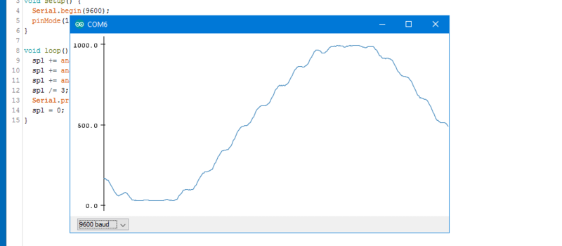
[LDX] first noticed the odd sounds coming out of his ceiling fan, regularly, on the hour and half-hour. Then he noticed that the lights were flickering as well. Figuring something was up, he built a logging power-line monitor to see if he could decode the shadowy signals and figure out what cryptic messages were being transmitted over the power lines. Naturally, he suspected the Illuminati were behind it.
Even if you’re not prone to flights of fancy, you might want to keep track of your power line because it can serve as an accurate long-run timebase for projects, or because it can tell you something about the overall health of the grid.
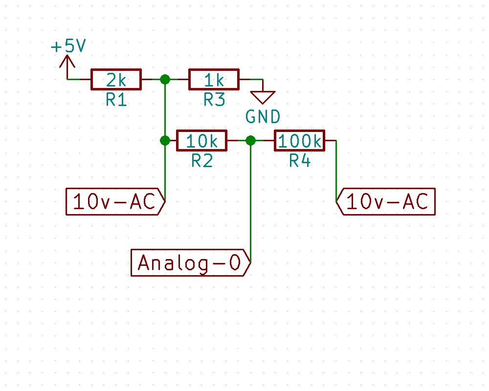 [LDX]’s circuit is as simple as can be. A 10 V AC transformer reduces the mains power down to something reasonable. A resistive divider chops this down further to the range that an Arduino can handle, and then another voltage divider biases the signal to the Arduino’s ADC midpoint. The plus-minus 10 V signal thus swings between 0 and 5 V, just.
SPOILERS! After confirming that there was a higher-frequency wiggle superimposed on top of the power-line frequency, he contacted the folks at his power company in Denver. got a tip in the comments to his project from someone named [Denver]. The system is called Decabit and it’s used to control street lights, hot water boilers, and other public infrastructure that might want to be coordinated to run when power is cheap or when it gets dark. The PDF that he links to explains it all, so you can take your tinfoil hat right back off.
But we still think it’s a fun project to look into the power lines. Who knows what other people will find? CON-spiracy!


Interesting, I didn’t know the name of that system.
We once own a home back in the Seventies that had the hydronic heating and domestic hot water connected such that the power company could exert some control during peak periods. Went through several Canadian winters in this place and I cannot say we ever noticed any time this was happening.
Sounds like an attack vector to me. Control the street lights with a device plugged in inside your home.
But, of course, they secured it against this sort of thing, right?
I did a quick search, and it seems this system is from the 1960’s.
One data package is 10 impulses (+1 start impuls) of 600ms and takes 6.6 seconds to send.
126 possible commands.
Can’t find any more information than that. There seems to be no way to adress individual endpoints.
How’s that for security.
Unless I did the math wrong (possible) you can communicate with 54 devices in each of the 22 segments of the K22 window. For each device (relay) you can tell it to be off or on. No toggling, just “you should be off” or “you should be on.”
Each communications packet has 10 bits plus a start bit. Each device is coded to respond to only five of those bits. If they are all on, it turns on. If they are all off, it turns off. It even sounds like you could control at least two devices at a time as long as the common bits of each need to be set to the same state. If two devices each use 5 completely distinct bits you could control both in the same packet.
At least that’s the way I read the spec.
(It’s worth noting, though I’m sure you get this, that a single “device” or “channel” would typically represent hundreds or thousands of separate devices of one type, each with their own relay. But it’s convenient to speak in terms of a single device.)
K22 and decabit are two different standards, which can be, but don’t have to be, combined.
Plain K22 uses the presence/absence of a carrier in each 7.5s time slot to command that channel on/off — one 3-minute packet defines the state of all 22 K22 channels. This is originally handled by electromechanical receivers with a synchronous motor, a dial, and some relays.
Plain decabit controls exactly one channel with each 6.6s packet, and all other channels keep their current states, thus it has many more channels than bits. Each packet has a start bit (high), plus 10 data bits. Of those 10 data bits, 5 are high, and the other 5 are low. Because of this constraint, there’s no way to control multiple devices at once — the 5 corresponding to the device you’re controlling are all either high or low, so the remaining 5 must be the inverse. And obviously, there are no devices assigned complementary patterns. There is some ability to control multiple devices with one packet, by way of master commands; I don’t fully understand it, but basically it allows one of several predetermined groups of channels to be switched on or off with a single command.
Combining them, you can put a 6.6s decabit packet in a 7.5s K22 time slot. The carrier will be on just about half that timeslot; it’s not clear if this would be reliably detected as “on” or “off” by a K22 receiver listening to that slot, but either way you could only use decabit during timeslots that happen to be on or off, respectively, or of course on reserved timeslots. More likely, it would not be reliable for K22 receivers, so you could use decabit in only reserved slots, to which no K22 receivers should be listening.
I’m not sure about 126 commands — could that be 126 channels, where each channel has an on code and an off code? Because the specifications I’ve seen (1 start, 10 data, with the data bits constrained such that there are always 5 high and 5 low) seem to allow 252 commands.
Anyway, it appears that, in practice, each decabit-controlled relay is controlled by two codes — a master code, and a specific code. Each master code corresponds to a certain list of specific codes; presumably the duplication is to allow fine-grained control for anticipated peaks, while still being able to shed massive load with comparatively few packets (6.6 seconds each) in an overload emergency.
This pdf has lots of interesting detail, including a full list of code assignments, for a particular NZ electric network: http://www.oriongroup.co.nz/assets/Customers/RippleSignalGuide.pdf
It references ways that their master/specific code mapping is not quite the same as the standard, but doesn’t fully make clear what the standard mapping is. Still, it’s a good starting point to understand the system; look for similar info from your own electric network for assignments in your area.
Yeah, its easy, just some stuff. Swistec makes such small boxes.
http://www.swistec.de/ankopplungen/
We do call it HDO here in the Czech Rep. Or “Ripple Control System”.
Já tušil, že se někdo od nás ozve.
Me too. Vašek :-)
It would take a lot of power and high power components to inject the signal into low impedance mains so I don’t think anyone is going to do it just out of curiosity.
Next step, decode the Decabit and see if he can figure out what the code for “control the street lights” is?
Then… inject his own?
Good luck with that. it is usually done at the local branch station with some pretty powerful equipment.
Check it here:
https://www.youtube.com/watch?v=XTTrWuFUvvA
or here, for more oldschool…
https://www.youtube.com/watch?v=_jWbNFX3KwI
Harmonics are fun….
Don’t show this to Photonic Induction.
ROFL, I think his motto is bigger, better, faster, more.
This motor / generator setup was used in the older telephone systems to generate the ring tone, busy tone, congestion tone and ring current (60 V AC).
They are far more reliable than a transistorized amplifier or oscillator. A telephone exchange might have to ring thousands of phones at the same time so the output may need to be tens of thousands of watts.
The different tones (frequencies) were created by different winding’s that had a different number of pole reversals to RPM and the interruptions were done by switching the low power field voltages off an on.
I suppose you’ve never heard of a dead man’s cable huh?
Power line communication
As old as the grid?
You can do nice things with it.
Strange it got noticed in the lamps and ceiling fan, they should filter it out.
If they can talk to the system, anyone can.
Still for the conspiracy nut, with all the abstraction of modern technology, how often do you unplug your tv when you’re not watching it. You’re phones left on charge, it can draw much more current to transmit further. Think of it this way, if they pay any attention to you, you must be doing something right.
There are lots of interesting signals out there if you know where to listen.
The transmit power of these kind of systems is usually very high, on the order of tens of kW. It may not be that easy to spoof over any distance.
Talking to the system seems to take more power than my pockets have money for by the looks of things.
The conspiracy nut, well I agree. If you drag attention to your self then they “may” use some intrusive methods. But if they already caught you doing something that bad, then you are already in trouble anyway.
Two types of conspiracy: The apparent bank robber destroying steel structures with heated aluminum foil and the list of engineering examples of how they may of did it, then the other where the “Aliens Did It!!!!”
The first being a conspiracy theory (plausible) and the second being the Bat Sh** Crazy conspiracy theory.
Signals, You get some interesting reception by just not trying. Too lazy to look, but do you need a license to receive (Non residential radio) signals, even accidentally through experimentation (Intentionally continuing to receive)i.e. bad circuit (amplifier) design in the UK?
Extract from wireless telegraphy act 2006:
“48Interception and disclosure of messages
(1)A person commits an offence if, otherwise than under the authority of a designated person—
(a)he uses wireless telegraphy apparatus with intent to obtain information as to the contents, sender or addressee of a message (whether sent by means of wireless telegraphy or not) of which neither he nor a person on whose behalf he is acting is an intended recipient, or
(b)he discloses information as to the contents, sender or addressee of such a message.
(2)A person commits an offence under this section consisting in the disclosure of information only if the information disclosed by him is information that would not have come to his knowledge but for the use of wireless telegraphy apparatus by him or by another person.
(3)A person does not commit an offence under this section consisting in the disclosure of information if he discloses the information in the course of legal proceedings or for the purpose of a report of legal proceedings.
(4)A person who commits an offence under this section is liable on summary conviction to a fine not exceeding level 5 on the standard scale.
(5)“Designated person” means—
(a)the Secretary of State;
(b)the Commissioners for Her Majesty’s Revenue and Customs; or
(c)any other person designated for the purposes of this section by regulations made by the Secretary of State.
“
Perhaps it is filtered out and some problem in the power grid or producer caused the flickering? I know that sometimes the normally very regulated power is either too low, to high or very noisy for a short period of time. Most wouldn’t notice as normal electronics isn’t too sensitive. Worst case IME were a few days when a high-amplitude noise were present and destroyed most incandescent bulbs at home, LED lights had no problem except one (Philips brand – relatively new too). Electronics didn’t care much though, AFAIK the switching PSU should handle all reasonable power noise so not that strange…
“Steelmill furnaces needs more power – nuclear power plant – retract control rods”
Wait for the fire sale.
http://www.elec.uow.edu.au/apqrc/content/technotes/UOW019_Tech%20Note%2014_AW_screen.pdf
The project doesn’t specify that it’s a power company in Denver, but instead someone named Denver pointed him to Decabit which solved the puzzle.
Slightly disappointing, because I live in the Denver area and was looking forward to having some fun with my local streetlamps.
You also looking forward to spending the best years of your life in jail?
For this he would need to get caught. But anyway, the required power is more than a typical household gets delivered.
You’re right! I actually live in Australia, apart from that its great that it got written up as I don’t think most people know about these things (or get annoyed by them).
Oh that’s funny. I’ll go fix it in the article. Thanks.
Well powerline communications shouldn’t be a surprise, but that circuit sounds “wasteful”.
If it was designed in the 1960s, it could well even be partly mechanical, synchronised motor (to the mains, handy!) sweeping past some contacts. Relay logic. Back then that’d be cheapest, now you’d just use a microcontroller.
There was a retrotechtacular a while ago on how Telex machines worked. Completely mechanical, including parallel / serial conversion (series of cams), coding the keyboard and decoding the printer, everything. All integrated in a clever way that was based around it’s needs. As well as stuff like early card punches, printers, all sorts, there used to be very ingenious computer stuff done with mechanics.
Since controlling street lights and boilers is the system’s only job, it does a pretty good job I think. No need to be efficient with bandwidth, there’s nothing else there. More important to be reliable on a large scale, and as simple and cheap to make as possible.
In the 60ies not only the cheapest, but I think semiconductors for several 10 kW were not invented. Vacuum tube equipment would not be that reliable for decades of operation. And probably also important: People from the power business are used to heavy electromechanical machinery and their reliability and maintenance.
yep, there’s not much that is more reliable than copper …
Q: What’s it made of ?
A: Copper
Q: And what else apart from copper is it made of
A: More copper
Rodalco2007 has a few videos on the Zellweger ripple injection.
https://www.youtube.com/results?search_query=Zellweger+rodalco2007
At a old job, we’d have the job of powering up / powering down huge pumps to move water between high / low points on demand from the grid. Basically as a battery.
We’d operate them via was basically was gprs modems and industrial control units. Controlling them over the actual power lines would of been awesome tho!
They changed over to GPRS over here years and years ago for controlling the power line branch switches and remote breakers. I barely got to see the wall of switches that was used to control the old control system – big grey metal box inset in multiple cabinets with black lines and diagrams like a Russian nuclear power station in miniature.
I scored a bunch of leftover SLA gel batteries and a few 12 volt switching regulators from the old switchgear.
The reason why they changed is because every time there was a short on the line the whole system tripped down, then they’d signal each relay up one by one to see if it would trip again. Takes a lot of time. The new radio relays would call you back on a fault and say where it is, so the fault can be isolated and the whole branch doesn’t have to go up and down multiple times to find it.
Not at Dinorwic? It’s the only place I’ve heard of that has such a system.
Nah, Severn Trent Water
like HART protocol in steroids!
This is basically the system that is used for switching between night/day rate electricity. The old analog kWh meters physically switched a gear to a different counter on recieving a particular overtone signal that tickles some resonant reeds. That’s why it’s non-toggling but a different signal is used to switch states.
Remotely operating the day/night switch allows the power company to switch on night loads in different branches at different times, so they don’t get everyone’s water heaters online at the same instant the clock strikes ten.
Toggling would also been too error prone. Imagine just one missed signal, it would mess up the switching until the next missed packet. There was no answer channel.
A slightly related but interesting protocol is X10 home automation control over power lines. Seen here in Appendix A:
http://ww1.microchip.com/downloads/en/AppNotes/00236B.pdf
I actually live in Australia and I had a hunch it was some sort of signal but my search on the ‘net for “power line noise” (or similar) turned up nothing so I thought I would write up a small project and make it fun, then [Denver] suggested Decabit and It made sense.
I haven’t contacted the power company (yet) and what I still don’t get is why it happens every 30 minutes (or every 15 minutes during some hours) since it summer here, we have the fans on 24/7, one of the fans is very noisy when the signal starts. “Once you hear, you cannot un-hear”
You could insert a filter into the fan supply. Either a lowpass or a notch.
If you make a complaint to the electricity provider then they can put a snubber (suppressor) on the pole. I don’t know if they charge for it or if it can fit on a UG box. I expect that the components to a low pass filter would be huge though. Do the math … pass 50Hz, block 200+Hz at 60 amps.
I wonder if any high-end consumer generators use Decabit, to tell home appliances like washers and fridges that have the capability to ease off for a few minutes.
The high load electrical devices would be –
Hot water heater: 600 – 2400Watt,
Air-conditioners: 1000 – 3600Watt,
and to a lesser degree –
Fridge compressors: 150 – 250Watt,
The heaters in a dish washer or cloths washer: 1800 – 2400Watt
It’s not really worth worrying about the fridge as it’s fairly low power and it’s not really worth worrying about the washers because your chance of them being *on* in the first place is limited.
However the air-conditioner is a very suitable appliance to load switch especially after a power outage because the start up current is much higher than the run current and even that can cause a secondary failure when bringing the power back on.
We have outages here from cyclones that are like your American tornado’s except they’re often 100 Miles wide or even more.
We also have fire tornadoes which are small like the American tornado but with fire – like this –
https://s-media-cache-ak0.pinimg.com/236x/4d/19/18/4d19189d9a7873bdec18850933b6d2d1.jpg
http://www.picaster.com/wp-content/uploads/2015/12/fire-tornado-700×466.jpg
They’re very dangerous on outback roads if you don’t have a 4 wheel drive because you have to get away from the road as fast as you can in your vehicle because of the drop bears. Drop bears normally just eat small mammals but a human is still an attractive meal to them so they will eat a human if they get a chance.
http://www.austmus.gov.au/drop-bear
Recent research (with pictures) shows that drop bears (Thylarctos plummetus) actually prefer to eat foreigners –
http://www.australiangeographic.com.au/news/2013/04/drop-bears-target-tourists,-study-says/
Sorry, I got a bit carried away there.
[RÖB], you are probably my favorite commenter. :D
https://en.wikipedia.org/wiki/File:Dropbear.jpg
And yeah, you got me LOL.
Thanks :)
I am in Australia and these control signals are used to control off-peek power to help with load regulation and probably other things as well but not street lights as they have daylight sensors.
I hear the tone through the air-conditioner when it’s on but I don’t tell anyone or fear that they may think I am loosing my mind.
Just a simple statement that the air conditioner is speaking in tongues, digitally, should probably be sufficient….
… for a preliminary assessment order.
I actually live in Australia, not Denver (It was [Denver] who commented on the project) if you take notice I would like to know how often yo can hear the noise. Where I live there is a substation a few km away and I get the noise every hour, half hour and in between, for example: 9:00am, 9:15, 9:20, 9:30, 9:45. Or only 6:00, 6:30, not at all at 2pm.
Some things may be different here because we have a hydro-electric power station here that I assume generates more power than is needed locally.
I only hear the interrupted tone when the air conditioner is on but the compressor is off and it seems to come from one of the fan motor winding’s. Through this limited observation window, I notice the tone in early mornings and in late afternoons and these times would correspond to peak demand periods.
Unfortunately I don’t have a scope so it would be hard for me to design a logging device as I don’t know the tone frequency or weather that frequency would couple across a standard transformer without too much attenuation.
If I knew those two things or even just the tone frequency then I could easily make a low voltage high-Q OP-amp band-pass/detector that connected to something like an ATmega328, serial FLASH ROM and time chip like a DS1302/DS3231. I could probably fudge it with a 50Hz notch filter and a slope filter but it would have to be functional first time or I wouldn’t be able to debug it without a scope.
Well, any such communication system has to make it across ordinary transformers in the electric grid without too much attenuation, else it wouldn’t get through to the waterheaters and such that use it. And of course, since that puts it squarely in audio frequencies, you don’t need a proper oscilloscope — you can use one of those dodgy software ‘scopes that uses your PC’s line-in. With appropriate current-limiting and isolation measures, obviously. From that, you should be able to spot the frequency well enough, and build a hardware detector as you discuss, or just do it all in software.
I *might* give this a go by using a uC as a scope on the low side of a step down.
But as for distribution network transformers being *ordinary* ??? they’re the furtherest from ordinary that I can imagine, bilifar infeeds, oil cooling, high q factor to match the mains frequency, inductive dampening for lightning strikes etc and they blow like a megawatt fuse – ie explode catastrophically.
In the videos you can see the injector (which is kWatts) is fenced off and has a conformal coated floor so it’s injecting at 12kV or above – most likely 27kV judging by the small number of PLCs.
The reason it needs such high power in the first place is that distribution transformers attenuate the signal strongly.
But anyway, I don’t have to do the ‘injecting’ and the signal gets here with enough energy to oscillate part of my air-conditioner so I might get away with using a small potted torroidal because it is a *lot* different to distribution transformers and has a much lower q factor and a much higher bandwidth.
@RÖB:
According to tests from a friend a normal small power transformer (5 to 10W range) has transmitted signals up to 15kHz quite well. The control signals here are in the range from 175Hz to 1050Hz. I am sure not the power transformers dampen the signal so much, but it is just loaded down by all the electrical loads in the grid. Think heater resistors, switch mode PSUs and probably also motors.
@[Martin]
I am tempted to use an AC plug pack (wall wort) so that my design starts at the barrel jack and I don’t have to worry about it being dangerous to anyone who want to make it and the main certification can just be purchased.
I will look later so see what I have in the junk box for an AC step down.
@[LDX] and [Martin]
I found this document for NSW –
http://www.resourcesandenergy.nsw.gov.au/__data/assets/pdf_file/0006/456189/SIR-Aug-12-Final.pdf
Section 6.4 relates to ripple control.
Figure 6.3 shows the the frequencies and where they are used in NSW.
I probably wouldn’t be interested in making something that can work with all frequencies because I can’t test or debug it for frequencies except the one I have here. I expect that the frequency used here is 1050Hz because I can hear it quite easily and I am old.
Can you tell me the frequency there and if it’s the same as here then I can make a logger that will work in both places. Otherwise I could make one for here and publish the math formulas for the filtering.
“Audible noise through speakers … can also be caused by ripple injection signals” – maybe the audiophiles with personal power lines have a point.
http://www.wsj.com/articles/a-gift-for-music-lovers-who-have-it-all-a-personal-utility-pole-1471189463
I do so hate paywalls.
I hate it more when people post links to paywalled sites. Are they not aware that the others can not read it or do they try to promote the site to generate subscriptions? So, is it just ignorance or on purpose?
Knowing this is fun stuff, but how about filtering it out so things like fans and aircons don’t make noise because of it?
Also in Australia – we have 5 ceiling fans running pretty much 24/7. With one fan the noise is very noticeable – especially at slower speeds, and I often thought that it sounded just like a data-burst. Now I know that is what it actually is. Possibly the capacitor speed-controls also have an effect on filtering.
Could the injection system be used to relay music or speech? Subliminal messages to all the kids…”Father Christmas is watching you…”
The capacitor speed control may easily resonate at the used frequency, this would explain the dependency on the setting. The old fashioned (but more expensive) autotransformer for control would be better in this case.
LDX says: I get the noise every hour, half hour and in between, for example: 9:00am, 9:15, 9:20, 9:30, 9:45. Or only 6:00, 6:30, not at all at 2pm.
I live in Durbanville (North-Eastern Cape Town) and our municipality (who provides the power) use a Zellweger system to switch off our hot-water heaters for a few minutes during peak demand times.
The realy-control in series with the heater will also go off and STAY OFF if the power to it goes off. So if you switch the house power off to change or repair something, the relay is off and will stay off. To prevent “cold water” problems the master-controller at the local sub-station sends a “switch on” message every 15 minutes, to bring any “off” controllers back to “switched on” status.
The system works very well. The period is so short that we have no hot water problems and the 15 minute “wake up” call that LDX notices reliably turn on any “off” relay. I have never heard any complaint about failures of any kind in the 25 years that we now have the system.
Sadly it looks like this project was removed – does anyobe have any details on how it was implemented?