There is one man whose hour-long sessions in my company give me days of stress and worry. He can be found in a soundless and windowless room deep in the bowels of an anonymous building in a town on the outskirts of London. You’ve probably driven past it or others like it worldwide, without being aware of the sinister instruments that lie within.
The man in question is sometimes there to please the demands of the State, but there’s nothing too scary about him. Instead he’s an engineer and expert in electromagnetic compatibility, and the windowless room is a metal-walled and RF-proof EMC lab lined with ferrite tiles and conductive foam spikes. I’m there with the friend on whose work I lend a hand from time to time, and we’re about to discover whether all our efforts have been in vain as the piece of equipment over which we’ve toiled faces a battery of RF-related tests. As before when I’ve described working on products of this nature the specifics are subject to NDAs and in this case there is a strict no-cameras policy at the EMC lab, so yet again my apologies as any pictures and specifics will be generic.
There are two broadly different sets of tests which our equipment will face: RF radiation, and RF injection. In simple terms: what RF does it emit, and what happens when you push RF into it through its connectors and cables? We’ll look at each in turn as a broad overview pitched at those who’ve never seen inside an EMC lab, sadly there simply isn’t enough space in a Hackaday article to cover every nuance.
RF Emissions Testing
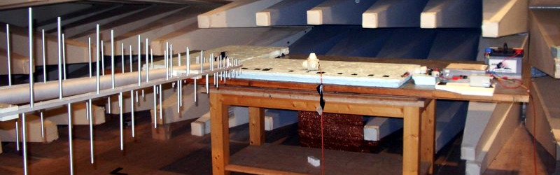
![The interior of a typical EMC lab showing the RF-absorbing baffles on the wall, the equipment under test on a wooden table, and a wideband log-periodic antenna. Techie2 [CC-BY-SA-3.0 ], via Wikimedia Commons.](https://hackaday.com/wp-content/uploads/2017/01/emcantenna.jpg)
In the lab itself the table is often mounted on a turntable and the antenna on a moveable gantry, such that the test can include measurements from all angles. A variety of antennas are likely to be used depending on the frequency, but you would expect to see a log-periodic antenna for use from HF up to UHF (about 1MHz to about 500MHz), and a Vivaldi antenna from UHF into the many GHz microwaves.
The test itself takes a few minutes as the computer does its GPIB magic, and the result you are given is a graph of intensity versus frequency with that crucial pass/fail red line over which your intensity trace must not stray. You’ll see quite a few intensity peaks, and you’ll find they will often correspond to internal clocks or data rates.
![This chunky ferrite probably means someone was defeated by the EMC lab. AlexJFox [Public domain], via Wikimedia Commons.](https://hackaday.com/wp-content/uploads/2017/01/ferrite_bead_filter.png)
It’s worth saying at this point that the most valuable feature of the EMC lab is its operator. Time in there isn’t cheap, but the guidance of a really helpful expert can make the difference between leaving with a device you can make pass the test and one that has no hope. You can learn from those people, as well as benefit from their advice.
RF Injection Testing
The other side of the RF testing coin are the injection tests. In simple terms, you are inducing large amounts of RF energy in all inputs to your device, and ideally you are hoping that it will neither be damaged or its operation compromised by this mistreatment. For instance, will AM modulation break through into any of your analogue circuits, will your processor reset itself, or will your digital data I/O be interrupted?
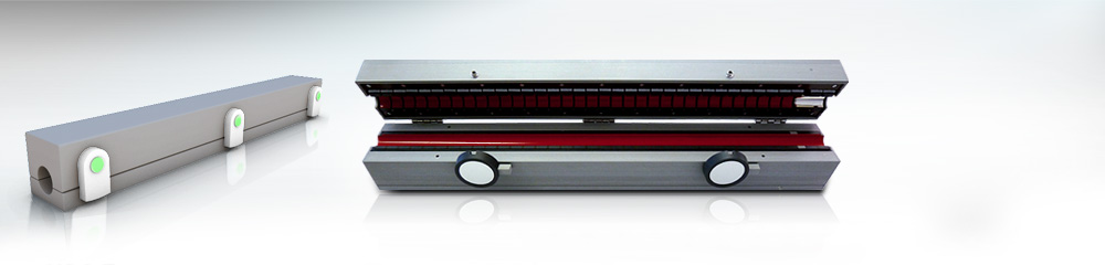
There are a variety of means used to induce the RF in your device, so the one I’m describing is merely the one I’m most familiar with. The Lüthi RF injection clamp is a long and narrow hinged box which when opened reveals a row of bisected ferrite cores that mate when the lid is closed. The cable is aligned with the centre of the cores, and held in place by spring lips built into the lid. There is an RF socket on the back that is coupled into the cores, making the device a very large and extremely wideband directional coupler.
The clamp is placed on an earthed ground plane and connected via an RF power amplifier to a signal generator, and a power meter is used to measure both the input power, and during calibration the induced power in a terminated wire passing through the clamp. The test requires an induced voltage of 3V RMS, so once the system has been calibrated the computer can alter the level from the signal generator to maintain this over different frequencies. A typical test will involve a scan of frequencies from the low kHz to around 100 MHz, with close observation for unusual behaviour from the device under test. A failure sends you running yet again for your stock of ferrites, with the added weapon of extra capacitive decoupling or sometimes simply screening. If you are lucky you can get to the bottom of any problems with a bit of clever design, if you are not luck you may have to accept adding the Huge Ferrite Of Shame on your cables.
There is something of a black art to designing out and fixing stray RF and EMC problems. RF never behaves in an orderly manner, or indeed as you expect it to. But learning something of the testing procedure or better still seeing the tests in action is a great help and goes a long way towards understanding more about the problem. Though I’m no EMC guru I first stood in an EMC lab in the early 1990s, and I always come away from the experience having learned something new!
If you enjoyed this article you should also check out [Bob Baddeley’s] piece on preparing a design for FCC certification.


Good stuff.
It should be worth noting that there are two classes of testing: Conducted and Radiated. For each class, there are two types of test: Emissions and susceptibility. You could have radiated emissions testing for instance, which looks into how much RF your device emits at different frequencies. Of those tests, there are a lot of variants. Looking through MIL-STD-461 can provide some insight into this.
I’d also like to point out that you can do precompliance testing from the comfort of your own lab. This can help shave off a lot of the cost of compliance testing at a lab. Its a good skill to have and is quite useful in tracking down spurious issues on your boards while you go through design, prototyping or troubleshooting.
Recommended reading: Electromagnetic Compatibility Engineering from Ott. https://www.amazon.com/Electromagnetic-Compatibility-Engineering-Henry-Ott/dp/0470189304
Nice article, I work in an EMC test lab and many of my customers have commented that getting through the tests can be daunting. It does depend on which standards are being applied and which directives those standards are for. There are often ways around meeting the requirements of the directives without meeting the test in the standard however more often than not it’s easier to pass the tests in the standard. I would say Jenny is quite correct in her article that knowing and understanding the tests, how they are performed to the standards being applied is critical. If you know which tests apply to your product and what those tests involves it is possible to account for it in the design stage. It’s much easier to artwork for extra components and not fit them than re-spin a design after a test has been failed. The amount of times I have had to add filtering components to a design and surge protection components to a prototype…..;)
The testing all depends on what the product is and which directives apply, from that decide which standards apply and then work out which tests apply – then read up on the testing and then design the product to meet the requirements of the test. Then perform the tests, pass (hopefully) without issue and declare the product to FCC or CE without too much hassle.
Thanks :)
It’s all very well having this testing for approvals but if is to be taken serious by the industry then there should be random testing throughout the production life of the device.
Look at the spaces on some Chinese made approved devices. Missing components that were installed when they were approved. The worst example of this I have come across was from an English manufacturer of 433 MHz radios. Once the product was designed and finished they sent a “special” pair of radios that were to be fitted for the approvals testing.
It depends on where the product is being sold in Europe. In the UK non-conformance is assessed by Trading standards and OFCOM both of whom are government funded. To my knowledge there have been very few prosecutions from non compliance for EMC or RED (radio equipment directive) stuff. I know that OFCOM have perform plenty of investigation work but the system is predicated on consumer complaint and securing a conviction.
It is incredibly difficult to prove EMC non compliance or explain why a product is non compliant for in simple terms to a magistrate or someone non technical so unless it is a very clear violation little can be done. Most of the convictions have been for electrical safety not EMC or RED – however in other European countries the agencies involved in compliance enforcement are directly funded from the fines levied and they are far more efficient in their applications of the standards.
Companies which develop products which do not meet the requirements are asking for trouble and it will only be a matter of time before issues arise….and are the bane of my employment!
There are moves afoot within trading standards in the UK to investigate more of the radio and EMC non-compliant products on the market so this situation may change soon
The products I’ve found myself working on tend to have been quite expensive, so manufactured very much within spec. And to those of us for whom a low noise floor is important, proper enforcement of emissions can’t come soon enough.
In Finland, Tukes (consumer safety bureau) does random testing also for EMC. Latest statistics I found were from 2011 but in that year, they issued 152 market bans for electrical safety, 7 for EMC and 5 for RoHS.
I have spent many hours in an EMC lab and once passed only because the test engineer at the lab shared some tips. Be nice to the people at the lab, they can save your product if they are in a mood to help.
Hopefully I’m always in the mood to help! I do know that some labs don’t offer free consultation and that makes it difficult. My lab does but not all do and I hear talk that it really depends on the person performing testing. As Bill wrote be nice to the test engineer! Bill ++
I have been in a EMC lab once. They had a set of coils and capacitors to help the customers to pass the test and try things to improve the design. Thank you Vojenský technický ústav pozemního vojska Vyškov.
Some labs hire people that just want to make your life miserable… just the nature of people. I have been through this ten times and counting now.
As I say, I’ve always found them a mine of helpful advice.
Wasn’t it the Blackberry that sent audio devices into a tizzy each time data was being transmitted? I always wondered how Blackberry got away with being such a dumpster of RF legally.
GSM phones are an example where it is supposed that the benefit for people is greater than the need to comply. They just change the compliance so it passed.
Or they change the susceptibility levels for other equipment that may be affected. the problem then is that older equipment was designed and tested to lower levels.
Phones transmit almost exclusively in their allotted bandwidth. The problem with GSM phones is that most audio equipment is not tested for sensitivity to interference, not that the phone is doing anything wrong.
Actually no.
It is true that the Blackberry shouldn’t be radiating appreciable power, but more importantly the audio devices should not be affected by RF.
If it’s not a radio, it shouldn’t respond to RF.
As the aticle sais, there are two completely different tests: One for Radiated emissions, amd one for Immunity.
EMC test levels are getting harder to pass and you really should start off at the design stage. read the standards that your product must pass and then design for this. Add options at different points in your circuit to add last minute fixes.
As the design progresses you should do cheap and quick tests to check if you have any issues.
Once you go for full blown testing on the final product then any changes can mean expensive redesign plus expensive re-testing.
So educate your designers and don’t leave it to the end. Build up a set of design rules that are aimed at EMC.
Having said that, you often find issues at final testing and so it’s prudent to allow time and cost for test over-runs.
Agree stockdam ++
I would agree that there are more meaningless stamps required by local political groups.
But seriously, passing unintentional-emission tests is very easy if you follow simple design practices, or put it in a metal box (or plated plastic) if you can’t figure out how to read ARRL books.
Indeed, a few hundred dollar pre-scan during design costs way less than failing a production model.
I wouldn’t agree that passing is very easy in all circumstances. I used to do the testing for our company, and it was extremely difficult to pass RE for a system that had 192 Fibre Channel transceivers running at 4.25 Gb/s. At that frequency, it’s very challenging to make the box tight enough to keep the emissions in it. It ended up requiring a complete redesign of the laser driver/post amplifier IC, which would have cost about $500k.
At the frequencies present in the circuit you mention I would say it is an extremely skilled job to ensure the device meet the requirements of radiated emissions. I also agree that the semi-conductor switching action internal to the electronics is probably the primary cause of such emissions and stopping that get out of the enclosure is very difficult due to the small wavelengths involved.
The use of special materials and case construction would be critical in that situation – making a case like a biscuit tin with folding overlapping edges with special gaskets would be where I would start. All cables would have to be screened and transmissions lines to reduce to emissions…it would be an exceedingly challenging project in my opinion – Well done if you got it through!
In that situation as the EMC test Engineer I have had to pull out every trick I know to get a device like that through!
True story. I helped work on a military controller product for a company in Florida. Florida, being Florida, has high heat and humidity, so static electricity is almost never a problem.
Well, that product needed to go into a chamber. To get to the gantry, you had to walk all over that conductive foam stuff. However, they placed wooden boards over the foam to make walking easier. Well, something was rubbing something, the triboelectric effect was in full force, and air conditioning had removed the humidity. The end result was that you could get 1/2 inch sparks off of your fingers by the time that you reached the gantry — I was worried about the device surviving being handled. Being military, we had big gigantic diodes on the I/O, but that was a lot of spark. Still the largest ESD sparks that I have seen, and I live in Colorado now.
Well the boards were defeating the purpose weren’t they?
I don’t think so. The conductive foam was part of the RF absorbtion for the anechoic chamber, the had nothing to do with static control.
Is this RN Electronics you’re writing about? I had no issues taking photos when I was last there. It was about 5 years ago now though so I guess protocols may have changed since.
I remember seeing the huge test chamber that had a turntable designed for testing EMC on a full size car, and the eerie silence inside the anechoeic chambers was also quite memorable – it was strangely difficult to hear the person next to you speak due to the foam RF absorptive material all over the walls.
animals with day vision have melanin pigmented layer behind the photoreceptors, to increase contrast at the expense of intensity… animals with night vision have a reflective layer behind the photoreceptors, to increase intensity at the expense of contrast (as it reflects to nearby sensors and illuminates the whole eyeball lowering black levels)…
although the rooms and other environments we typically sit in are not parts of our body, your comment makes me compare it with day/night vision, we assume increased intensity by reflections at the expense of fidelity (spectral response of the room)
We’re just battling with EMC issues as we bring our (Free and Open Source) product, the Ultimate Hacking Keyboard to the market. Relevant blog post at https://ultimatehackingkeyboard.com/blog/2017/01/20/the-first-sample-batch-and-emc-test
…where software guy, unhappy at being micro-managed by hardware guy, witnesses Karmic REVENGE!!!!
Revenge for what?
The software guy just forgot to reduce the drive strength (as he was told, but called it micro management) at the slower ports, so even 100kHz signals were driven with 1ns edges, causing the radiated emissions issues. Or to make a really synchronous FPGA design everything is clocked with 200MHz although most stuff happens with 10kHz or less. :-)
Unfortunately these are true stories.
I’m in the process of prototyping a device which would (hopefully) end up as a product. Can you suggest any “simple” methods for testing for most obvious EMC issues without a full lab test? Anything better than educated guessing?
Well it depends on the device and how it’s powered and which tests apply. If you want to perform a quick and dirty emissions you can use a simple search coil and an oscilloscope to test for Radiated Emissions. Set the scope to the lowest voltage scale you can and a sensible timebase and then wave the coil over the PCB under test. Where you see signals on the scope will be where there are areas of RF emitting from the PCB – then look at the circuit assess whether it’s a problem and make changes. When you make changes repeat the scope measurement and see if there is an improvement.
To do EMC pre-compliance properly for emissions testing you will need access to a Spectrum Analyser, a method of filtering out of band signals and an RF probe. Some meaningful measurements can be made this way as long as the person performing measurements is capable of using the instruments and understanding the results. The equipment can be hired, the experience is only obtained with time and exposure.
If the device is mains powered the emissions coming back onto the mains needs to be measured and for that a special network known as a LISN is needed – a line impedance stabilisation network as well as the pre-filter (preselector) and a spectrum analyser.
All of the equipment can be hired but the testing is often difficult to perform without experience. I would suggest you found a local lab and request pre-compliance testing and negotiate a rate. The lab I work for offers such a service but I don’t think it’s correct to publicise on here. Google should be able to point you towards a local lab.
Good luck!
thanks :)
Compliance testing (the basic stuff) really needs to go to the franchise model. It’s too expensive for a short automated test. We need tons of small labs competing for business. Would be attractive for older engineers or those who want to be self-employed and independent.
The cost of the test equipment and chambers needed to perform reasonable measurements is far too expensive and would be an unattractive investment for anyone without experience in RF. Franchising just wouldn’t work. Nice idea though.
Perhaps more labs would mean more mass production of test equipment.
With respect I don’t think you quite understand the nature of the measurements being taken. Radiated Emissions from a printed circuit board are often in the region of 30 dBµV which when converted into a real value is 31.623 µV. The best oscilloscopes from Lecroy do not measure down to such low levels. A spectrum analyser is the instrument of choice as they are capable of making such measurements and they contain very high specification amplifiers in the analogue front end.
The range of frequencies required to be measured for most products these days is very high – measurements require the 3rd harmonic of any clock frequency present on the board to be measured which for a wifi or bluetooth device is 9.6 GHz with the fundamental frequency of bluetooth or wifi is 2.4 GHz applying the standard CISPR 22 or CISPR 11. So a spectrum analyser with a noise floor below 30 dbµV with a measurement range above 10 GHz is required. The rest of the internal electronics and processing required to display those signals faithfully and accurately requires some of the best electronics components money can buy. This coupled with development time means the spectrum analysers used for this work cost thousands in whatever currency you care to choose.
I checked Ebay – a 13 GHz spectrum analyser from Anritsu was 6900 USD
http://www.ebay.com/itm/Anritsu-MS2723B-Handheld-Spectrum-Analyzer-9KHz-to-13-GHz-/142212730388?hash=item211c8a0e14:g:h3kAAOSw241YUjKH
Rohde and Schwartz (The best imo) was on sale for 16000 USD
http://www.ebay.com/itm/Rohde-Schwarz-R-S-FSV13-Signal-and-Spectrum-Analyzer-10-Hz-to-13-6-GHz-/141606568522?hash=item20f868c24a:g:xbMAAOSwNSxVBqpB
Second hand units are often used and reused and recalibrated all the time in an effort to reduce costs. The accuracy of the measurements is paramount as it is used to prove compliance to standards….a poor measuring instrument is no defence in non compliance.
More labs will not reduce the cost of the instruments but it will make money for the people selling the kit! Rhode and Schwartz or Anritsu and Keysight would be more than happy to sell more equipment!
I have tried to use a Rigol spectrum analyser recently which was considerably cheaper than the other options. It was an excellent budget spectrum analyser and could be used to make basic RF measurements, profile filters and antennas. It couldn’t be used for EMC work because unfortunately it didn’t have a low enough noise threshold to be able to distinguish emissions from the background.
Don’t get me wrong I would like everyone to be able to buy good cheap test equipment but unfortunately EMC testing is a high accuracy requirement and budget instruments don’t cut the mustard.
I really would like there to be more options as a designer I can’t afford to get my products certified, as an EMC and RF test engineer I try to provide as cheap a service as possible but the capital investment cost in running a lab is very high and is reflected in the price of testing. If you factor accreditation and calibration into that then it gets higher still.
My only solution is to advise designers to learn the standards and apply good design decisions from the outset – design with passing the tests in mind. Know what the tests are and how the testing is performed and then your designs can be prepared which minimises tests costs and test time and gets a design closer to market as soon as possible.
Mass production of anechoic test chambers? :-)
I would think you could set up a lab/chamber for <$200k and cheaper for an OATS and if you did 5 tests per day 250 days per year $500/test you would have $625,000 in revenue
I think you need to look into the costs of a semi-anechoic chamber… 200k would not come close. I use a Gtem cell which is a similar method but cheaper to implement…harder to calibrate and cost around 30k.
A spectrum analyser and preselector, lisn and cables etc are another 20k
A screened room another 30k…
Rf Amplifiers, 60k
Surge, FTB and Dips generators 30k
Coupling decoupling networks and clamps 2.5k
ESD gun – 2k
Software 5k…
Rent space to store / use kit 3k / month…
Insurance and calibration costs 5k
Ok…i take it back 200k would get you started… You would not be accredited and charging 500 per test is light for some of the tests in terms of time. Reporting takes time too…
I don’t know about you but we don’t have customers in everyday paying up front… There are taxes and rates to consider and book keeping and factoring too…heck get a bank to loan you the money… I’ll help you get started… More the merrier
Accreditation is a problem there are too many requirements against a small lab. That is why franchise model could help with standardized training, procedures, volume equipment buying, and deal with agencies. It would be OK for the smallest setups to only offer RE/CE tests in unlicensed bands for devices smaller than 1cuft. Best way to get more compliance is by cheaper testing/certification.
Pretty much everything can be automated from equipment control to data collection to report generation and prompts for all human tasks.
It is tempting to give it a try.
I think your model would work for pre-compliance testing, but not the actual compliance testing. With pre-compliance testing you can step in and test at every phase, and I have found we could have a confidence level of >99% of final compliance, if you do pre-compliance testing. Just be assured you will have crying project managers all over you, lol
That expensive calibrated equipment is quite cool, last time I was in the lab we opened the cap on a 1″ access hole into the anechoic chamber and immediately saw a 900MHz spike on the spectrum analyzer from the local GSM towers.