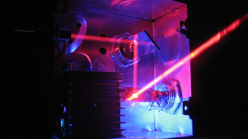
We’re suckers for any project that’s nicely packaged, but an added bonus is when most of the components can be sourced cheaply and locally. Such is the case for this little laser light show, housed in electrical boxes from the local home center and built with stuff you probably have in your junk bin.
When we first came across [replayreb]’s write-up and saw that he used hard drives in its construction, we assumed he used head galvanometers to drive the mirrors. As it turns out, he used that approach in an earlier project, but this time around, the hard drive only donated its platters for use as low mass, first surface mirrors. And rather than driving the mirrors with galvos, he chose plain old brushed DC motors. These have the significant advantage of being cheap and a perfect fit for 3/4″ EMT set-screw connectors, designed to connect thin-wall conduit, also known as electromechanical tubing, to electrical boxes and panels. The motors are mounted to the back and side of the box so their axes are 90° from each other, and the mirrors are constrained by small cable ties and set at 45°. The motors are driven directly by the left and right channels of a small audio amp, wiggling enough to create a decent light show from the laser module.
We especially like the fact that these boxes are cheap enough that you can build three with different color lasers. In that case, an obvious next step would be bandpass filters to split the signal into bass, midrange, and treble for that retro-modern light organ effect. Or maybe figuring out what audio signals you’d need to make this box into a laser sky display would be a good idea too.


Now all I need to do is put “She blinded me with science” on the turntable.
Miss Sakamoto, you look beautiful tonight!
+1
So the motors are essentially galvos anyway. A galvo can’t rotate all the way around, typically a few degrees but much faster response than a motor. Which makes me think, why not solder two loudspeaker braided connections to the 2 appropriate segments of the commutator. Now with no brushes the motor is used in a restricted range of motion and really is a galvo.
The spring used to center the range of motion is the tricky part. Here is where the mechanical resonance of the spring and mass will make it respond to a narrow range of low bass notes, which is what you have. Fat chance of getting these to respond to midrange yet treble. Still a great audio visual scene. Smaller motors and mirrors might make it work at higher frequencies, think pager motors and clock-springs or cassette pressure pad springy things! Using both types of motors will make for more a interesting scene.
Years ago at a ham-fest I got a stripped down Laserdisc deck with two orthogonal galvos and a He-Ne laser. It will do about 30 degrees of similar x-y display. Now brainstorming, I think a current drive (put the load in the feedback path of a power op-amp) would broaden the response range of either device. While not positional feedback it’s far simpler to do.
In the comments he mentions running it through frequency sweeps with pretty good results.
The intro shows that he is getting very good response in the mid ranges. I think the bass is just overwhelming the signal because it longer duration (period) and amplitude and therefor stored rotational momentum.
His output is driven in a linear way and human hearing is logarithmic. It would be much easier to associate the image to the sound if he had a linear to log converter in the drive stage. He could also attenuate the bass at the same time.
If the bass was filtered out, delayed and inverted and then used as feedback then a lot of the momentum issues would be alleviated.
I don’t think direct connection to the commutator is an advantage. The three polls are 120 degrees apart and commutator transitions are 60 degrees apart. It doesn’t look like he is using more than 60 degrees deflection so I assume he has aligned the motors so there are no commutator transitions.
It would be interesting to see what would be achievable with some filtering and some compensation for momentum issues.
Here is a PID that would be perfect for this but may take some ‘tuning’.
http://www.ecircuitcenter.com/Circuits/op_pid/image002.gif
Full description – http://www.ecircuitcenter.com/Circuits/op_pid/op_pid.htm
Were you expecting to see code??? This is essentially a fixed function analog computer.
To calibrate the PID you can use a crosshatch or dot pattern that shown non-linearity. You could make this test signal wit some code on a PC and output it as WAV.
I saw my first laser show in 1978 at a local pop festival where i volunteered. Lasers were still very high tech and a new thing back then. The festival had booked a cello player who used a laser beam to project the waveforms he produced on the nightsky. As luck would have it, I was asked to help him set up his equipment and he let me fool around with it after we finished setting up. Truly mindblowing
Respect for really good safety/caution/warnings throughout the project.
i second the idea of hooking this up to a colour organ.
pity it would need 3x the amplifiers.
… with auto-level-control on the input,
sidewalk-disco of course ;)