Retrofitting An Amstrad CPC6128 With A Floppy Emulator

In the home computer boom of 1980s Britain, you could describe Amstrad as the third-placed home-grown player after Sinclair and Acorn. If you were a computer enthusiast kid rather than a gamer kid, you wanted Acorn’s BBC Micro, your parents bought you Sinclair’s ZX Spectrum because it was cheaper, and you thought the Amstrads were cool because they came with a better monitor than your family’s cast-off 1970s TV.

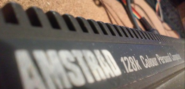
Amstrad were not a computer company headed by a technical wizard, instead they were a consumer electronics company whose founder [Alan Sugar] had a keen nose for the preferences of the consumer. Thus the Amstrad machines were different from some of their competitors: they were more polished, more appliances than experimental tools. Mass storage devices such as tape decks and floppy drives were built-in, every Amstrad came with its own dedicated monitor, and keyboards were decent quality as you’d see on a “proper” computer.

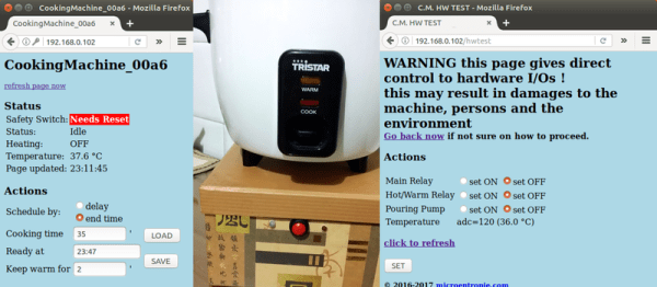
The high-end Amstrad model was the CPC6128. It came with a 3″ floppy drive, and of most interest, it could run the CP/M operating system. If your parents bought you an Amstrad CPC as a 1980s teen, it wouldn’t have been this one, so they are considerably less common than their 64k brethren with the cassette deck. One has found its way into [Drygol]’s hands though, and because the vintage 3″ floppies are unobtainable nowadays he’s fitted a floppy emulator board that stores data on an SD card.

In a sense, in that this is simply the fitting of an off-the-shelf board to a computer, it’s Not A Hack. But misses the point. This is an unusual home computer from the 8-bit era and his write-up is as much a teardown as it is  a howto. We don’t often get to see inside a 6128.

Fitting the board required the fabrication of a cable, with some very neat soldering work. The board has an LCD display, which is mounted in the floppy opening with a 3D printed bezel. The result is a very usable retro computer, without too much in the way of wanton remodeling.

This is probably the first real Amstrad 6128 we’ve shown you, but that hasn’t stopped enthusiasts making a clone with original chips, and another on an FPGA.


Ultrasonic Raspberry Pi Piano

Cheap stuff gets our creative juices flowing. Case in point? [Andy Grove] built an eight-sensor HC-SR04 breakout board, because the ultrasonic distance sensors in question are so affordable that a hacker can hardly avoid ordering them by the dozen. He originally built it for robotics, but then it’s just a few lines of code to turn it into a gesture-controllable musical instrument. Check out the video, embedded below, for an overview of the features.

His Octasonic breakout board is just an AVR in disguise — it reads from eight ultrasonic sensors and delivers a single SPI result to whatever other controller is serving as the brains. In the “piano” demo, that’s a Raspberry Pi, so he needed the usual 5 V to 3.3 V level shifting in between.

The rest is code on the Pi that enables gestures to play notes, change musical instruments, and even shut the Pi down. The Pi code is written in Rust, and up on GitHub. An Instructable has more detail on the hookups.

All in all, building a “piano” out of robot parts is surely a case of having a hammer and every problem looking like a nail, but we find some of the resulting nail-sculptures arise that way. This isn’t the first time we’ve seen an eight-sensor ultrasonic setup before, either. Is 2017 going to be the year of ultrasonic sensor projects? Continue reading “Ultrasonic Raspberry Pi Piano”

How Many Watts Are You Using?

One of the best smart home hacks is implementing an energy monitor of some kind. It’s easy enough to say that you’re trying to save energy, but without the cold hard data, it’s just talk. Plus, it’s easy and a great way to build up something DIY that the whole family can use.

[Bogdan] built up a simple whole-apartment power monitor from scratch over the weekend, and he’s been nice enough to walk us through the whole procedure, starting with picking up a split-core CT sensor and ending up with a finished project.

The brains of his project are an ESP8266 module, which means that he needed to adapt the CT sensor to put out a voltage that lies within the chip’s ADC range of 0 V to 3.3 V. If you’re undertaking an energy monitor project, it’s as easy as picking the right burden resistor value and then shifting the ground-centered voltage up by 1.6 V or so. We say it’s easy, but it’s nice to have a worked example and some scope shots. The microcontroller reads the ADC frequently, does a little math, and you’re done. Continue reading “How Many Watts Are You Using?”

Hackaday Prize Entry: A Complete Suite Of Biomedical Sensors

The human body has a lot to tell us if we only have the instruments to listen. Unfortunately, most of the diagnostic gear used by practitioners is pricey stuff that’s out of range if you just want to take a casual look under the hood. For that task, this full-featured biomedical sensor suite might come in handy.

More of an enabling platform than a complete project, [Orlando Hoilett]’s shield design incorporates a lot of the sensors we’ve seen before. The two main modalities are photoplethysmography, which uses the MAX30101 to sense changes in blood volume and oxygen saturation by differential absorption and reflection of light, and biopotential measurements using an instrumentation amplifier built around an AD8227 to provide all the “electro-whatever-grams” you could need: electrocardiogram, electromyogram, and even an electrooculogram to record eye movements. [Orlando] has even thrown on temperature and light sensors for environmental monitoring.

[Orlando] is quick to point out that this is an educational project and not a medical instrument, and that it should only ever be used completely untethered from mains — battery power and Bluetooth only, please. Want to know why? Check out the shocking truth about transformerless power supplies.

Thanks to [fustini] for the tip.

Lens Mount

X-Ray Imaging Camera Lens Persuaded To Join Micro Four Thirds Camera

Anyone who is into photography knows that the lenses are the most expensive part in the bag. The larger the aperture or f-stop of the lens, the more light is coming in which is better for dimly lit scenes. Consequently, the price of the larger glass can burn a hole in one’s pocket. [Anthony Kouttron] decided that he could use a Rodenstock TV-Heligon lens he found online and adapt it for his micro four-third’s camera.

The lens came attached to a Fischer Imaging TV camera which was supposedly part of the Fluorotron line of systems used for X-ray imaging. We find [Anthony’s] exploration of the equipment, and discovery of previous hacks by unknown owners, to be entertaining. Even before he begins machining the parts for his own purposes, this is an epic teardown he’s published.

Since the lens was originally mounted on a brass part, [Anthony Kouttron] knew that it would be rather easy to machine the custom part to fit standardized lens adapters. He describes in detail the process for cleaning out the original mount by sanding, machining and threading it. Along the way you’ll enjoy his tips on dealing with a part that, instead of being a perfect circle on the outside, had a formidable mounting tab (which he no longer needed) protruding from one side.

The video after the break shows the result of shooting with a very shallow depth of field. For those who already have a manual lens but lack the autofocus motor, a conversion hack works like a charm as well.

Continue reading “X-Ray Imaging Camera Lens Persuaded To Join Micro Four Thirds Camera”

Little Laser Light Show Is Cleverly Packaged, Cheap To Build

We’re suckers for any project that’s nicely packaged, but an added bonus is when most of the components can be sourced cheaply and locally. Such is the case for this little laser light show, housed in electrical boxes from the local home center and built with stuff you probably have in your junk bin.

When we first came across [replayreb]’s write-up and saw that he used hard drives in its construction, we assumed he used head galvanometers to drive the mirrors. As it turns out, he used that approach in an earlier project, but this time around, the hard drive only donated its platters for use as low mass, first surface mirrors. And rather than driving the mirrors with galvos, he chose plain old brushed DC motors. These have the significant advantage of being cheap and a perfect fit for 3/4″ EMT set-screw connectors, designed to connect thin-wall conduit, also known as electromechanical tubing, to electrical boxes and panels. The motors are mounted to the back and side of the box so their axes are 90° from each other, and the mirrors are constrained by small cable ties and set at 45°. The motors are driven directly by the left and right channels of a small audio amp, wiggling enough to create a decent light show from the laser module.

We especially like the fact that these boxes are cheap enough that you can build three with different color lasers. In that case, an obvious next step would be bandpass filters to split the signal into bass, midrange, and treble for that retro-modern light organ effect. Or maybe figuring out what audio signals you’d need to make this box into a laser sky display would be a good idea too.

Continue reading “Little Laser Light Show Is Cleverly Packaged, Cheap To Build”

The Internet Of Rice Cookers

You’d be forgiven for thinking this was going to be an anti-IoT rant: who the heck needs an IoT rice cooker anyway? [Microentropie], that’s who. His rice cooker, like many of the cheapo models, terminates heating by detecting a temperature around 104° C, when all the water has boiled off. But that means the bottom of the rice is already dried out and starting to get crispy. (We love the crust! But this hack is not for us. This hack is for [Microentropie].)

So [Microentropie] added some relays, a temperature sensor, and an ESP8266 to his rice cooker, creating the Rice Cooker 2.0, or something. He tried a few complicated schemes but was unwilling to modify any of the essential safety features of the cooker. In the end [Microentropie] went with a simple time-controlled cooking cycle, combined with a keep-warm mode and of course, notification of all of this through WiFi.

There’s a lot of code making this simple device work. For instance, [Microentropie] often forgets to press the safety reset button, so the ESP polls for it, and the web interface has a big red field to notify him of this. [Microentropie] added a password-protected login to the rice cooker as well. Still, it probably shouldn’t be put on the big wide Internet. The cooker also randomizes URLs for firmware updates, presumably to prevent guests in his house from flashing new firmware to his rice cooker. There are even custom time and date classes, because you know you don’t want your rice cooker using inferior code infrastructure.

In short, this is an exercise in scratching a ton of personal itches, and we applaud that. Next up is replacing the relays with SSRs so that the power can be controlled with more finesse, adding a water pump for further automation, and onboard data logging. Overkill, you say? What part of “WiFi-enabled rice cooker” did you not understand?