With the availability of cheap modules, it has become easy to hack/make stuff at home and home appliances see the most creative hacks of all. In one such hack, [Vadim] takes the DIY route to adding battery backup to his gas heater.
His existing unit operates on two D-type batteries which need to be replaced once they are depleted. [Vadim] wanted to implement a reversible method since he lives in a rented place. He replaced the original cells with battery adaptors and brought out the connections using two wires. He then proceeded to add two cellphone batteries with a TPS54233 regulator so as to supply the desired voltage to the gas heater. This is interesting since the module used is an official Texas Instruments EVM instead of the traditional eBay purchase.
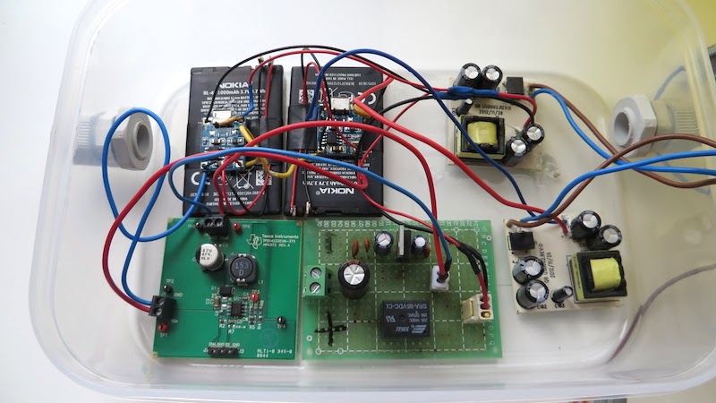
The batteries in question are charged using modules based on the TP4056 which in turn are fed 5V from power supply modules. The DC voltage is coupled with a LM1117 to provide power to the heater from the mains and the switch over is accomplished using an SPDT relay. The enclosure is a humble box which resembles a plastic food container and is fitted with PG9 cable glands along with a fuse holder to boot. Take a look at the original post for a plethora of images and details of construction.
This an excellent example of a project that came together using available parts to solve a problem without the frills. The DIY fish feeder is another example of a project with functional design and is a great example of DIY.


Uh, far be it from me to usually inject negativity into other people’s hacks, but couldn’t the same functionality be had by simply using decent NiMH D-cell batteries and a mains-powered current-limited constant-voltage supply that keeps them at some ~1.2V/cell, with a diode to prevent reverse-discharging in the event of a power outage? As it is now the author’s got Li-ion degradation to worry about and more components that have the potential for failure. Or have I (as is most likely) missed out on some key part of the build that necessitates the increased complexity?
“This an excellent example of a project that came together using available parts to solve a problem”
Well, then everything makes a lot more sense =)
Yeah, I’ll admit that’s a better decision. I’ll go for it when this thing breaks, thanks!
Nothing wrong with hacking something together with what’s at hand as a band-aid solution
Oh, I completely forgot that I did try to feed 2 rechargeable 1.2V batteries into this thing, but even at full charge that won’t get spark going…
Aw, that’s too bad =( I guess you could always go for three 1.2V batteries and a silicon diode in series to get some 3*1.2-0.7~=2.9V, but that’s not nearly as elegant a solution…
I have a few questions about the build:
1) Why the dual Mains-5vDC converters? Was 1 just not enough?
2) Why the second power regulator and switching circuit? Could you not just run the power from the batteries? I assume that the little battery charger boards dont provide power AND charge at the same time.
As a second more generic question: what do you think the runtime would be with the cell phone batteries?
Hi! I do have an answer to at least one of your questions:
1) I only had a buck converter, that’s where 2 batteries instead of 1 come from. One cell can theoretically discharge to 3.3v and less, and that would call for a buck-boost converter that I didn’t happen to have..
Now, the charger’s GND is at the same potential for input (5V) and output (battery). If I had powered both chargers from one 5V PSU that would result in second battery short-circuited.
2) My gas heater was designed to run on 2 AA batteries or 3 volts. One lithium cell can have a voltage across it up to 4.2V. I only dared to overvoltage a little. So, I guess, if my balls were just a tad bigger, I would pull this off :-)
As for the runtime, I’ll admit I didn’t do the math, but practically guessing I can tell it’s waay longer than power outages in the most remote places. It will obviously also depend on how frequently you use hot water.
“With the availability of cheap modules, it has become easy to hack/make stuff at home and home appliances see the most creative hacks of all.”
Long as safety is observed. One wants to live long enough to enjoy their hack after all.
Vadim should respect that it is actually not his heater, but his landlords heater. Should some aspect of his screwing around catch on fire, or fail in freezing weather, than what will he have to say? Sorry I burnt your house down, or sorry I froze your pipes?
If the rented space is heated with a device that takes two batteries, and they periodically die, deduct the cost of two new ones from the rent or tell the landlord the heater is not working and let him change them.
In the house I let out I have many battery powered smoke and CO detectors and it is in the lease that they hit the test button every month and send in a pre printed check box report along with the rent check. If a detector fails to work, I am happy for them to deduct the difference from the rent, or come and change the battery for them.
I am not against screwing around, but do it with your own stuff.
He (the landlord) is actually fine with my tinkering so long as I don’t modify anything permanently and observe safety (AC line fuse + PTC fuse for each LiIon cell). Oh, and the device has a power switch to avoid failures while there’s no one home that switches off the charging circuit (the area that is most likely to fail and catch fire is around batteries, obviously).
The bottomline is, lots of things can go wrong fatally, even more innocuous ones than a diy mains-powered circuit, you just have to observe all precautions like a sane human being to stay on the safe side.
>more innocuous ones than
whoopsie, one extra word here :) Meant to say
>more innocuous than
The linked Author’s schematic shows two “3.7V” Li-Ion batteries in series (2S) EACH charged by a separate Chinese TP4056 charger chip. But BOTH TP4056 charger chips share a common input voltage and ground. But the grounds shown on the Author’s schematic do NOT match what is shown on the TP4056 datasheet.
TP4056 charger chip datasheet (English) from NanJing Top Power ASIC Corp is here:
https://dlnmh9ip6v2uc.cloudfront.net/datasheets/Prototyping/TP4056.pdf
Does this REALLY work?
I find it hard to believe this can really charge two SERIES (2S) Li-Ion cells with two series TP4056 charger chips from a single source and single source ground.
Comments anyone? Does anyone have an LTspice (preferably) compatible model for the TP4056 so I can test it in simulation?
The two 5V supply modules appear to have small transformers.
The presence of a rectifier at the AC inputs to these modules suggests that these are switching devices, making it likely that the yellow transformers are high frequency/switch mode and are providing outputs that are galvanically isolated from the inputs, i.e. floating, with respect to mains ground and therefore each other. This allows them to be used to charge two batteries in series.
One of the 5V supplies is used as a power source for the heater control module when mains power is available to power the relay, and without mains power, the relay switches over to the battery supplied buck converter, it seems.
Basically, it seems to be behaving like a UPS.
Hot water UPS WAF = +10
@e, Thanks for the clarification, I missed the AC input split (my bad). Those Traco modules are expensive. It’s impossible to really tell from the Author’s terrible schematic resolution. But for example here’s a single in/out 5V-1A Traco AC/DC isolated switching module that costs around $40 bucks (ouch). The link is to a Mouser page, the Traco Web-site is a nightmare to deal with IMO.
http://www.mouser.com/ProductDetail/TRACO-Power/TMLM-05105/
The linked-above part may not be the part used by the article’s author – just an example.
Best Regards, David
I recently had to troubleshoot a very similar battery powered gas hot water heater that was externally mounted and supplied with gravity fed water and a 12V pump. There were multiple points of potential failure.
1) the plastic battery compartment can develop some corrosion around the spring terminals if it is exposed to moisture or rain, limiting available current to initiate turn on, which requires power for both the gas solenoid valve and ignition circuit/module.
2) similarly, the ends of the D cell batteries can also develop some rust over time, increasing resistance.
3) the power switch on the underside of the unit I dealt with can also develop corrosion internally with moisture/environmental exposure over time. The symptoms of this are initial gas flow and ignition when a water pressure change triggers the control module, but failure after 20-30 seconds, when I suspect the control module’s internal smoothing capacitor is depleted and insufficient current flows through the high internal resistance of the power switch and or battery module spring terminals. This was fixed by simply toggling the power switch a few times, after which the unit was able to remain on after ignition.
4) the unit I looked at is triggered by an increase in water pressure sufficient to trip a microswitch actuator through a membrane. Insufficient water pressure going in will fail to trigger the control unit, thereby failing to initiate gas flow and ignition.
I plan a similar solution to the linked author’s, except I will supply power to the unit with a LM317 regulator a few seconds prior to energizing the 12V DC supply driving the cheap ebay 12V pump. The pump is necessary to supply enough pressure to trigger the microswitch reliably.
A microcontroller will be used to stage the turn on with relays, i.e.
1) supply 12V to the LM317 supplying 3V to the control module (instead of relaying in 2 D-cells) for a few seconds prior to step 2)
2) 12V to the inlet solenoid installed upstream of the 12V pump to prevent flooding/catastrophic failures
3) 12V to the pressure pump
For those living in frost prone areas, the option of a stage 4) following use of the heater is installation of an additional solenoid to
4) drain the unit of water to avoid freezing, also controlled by the microcontroler
I wouldn’t put those LiIon charging boards on the batteries itself – 1) they tend to heat up, unless you decreased their charging current by swapping a resistor, I think it’s going to at least lower the lifetime of these batteries 2) if there are any sharp leads left underneath after soldering wires in holes of the charging board, there’s a chance of puncture, and LiIon pouch cell punctures can get nasty =(
Other than that, great work – and keep on hacking!