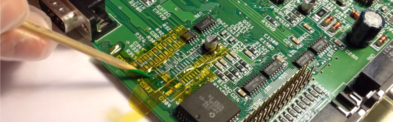
What do you do when your motherboard is covered in electrolytic grime, has damaged pads and traces that are falling apart? You call [RetroGameModz] to work their magic with epoxy and solder.
While this video is a bit old, involved repair videos never go out of style. What makes this video really special is that it breaks from the common trend of “watch me solder in silence” (or it’s close cousin, “watch me solder to loud music”). Instead, [RetroGameModz] walks you through what they’re doing, step by step in their repair of a motherboard. And boy do they have their work cut out for them: the motherboard they’re working on has definitely seen better days. Specifically, it was better before corrosion from a leaking electrolytic capacitor and the well-meaning touch of its owner.
After a quick review of the damage, all of the components are removed from the battle zone. Then the cleaning begins, taking special precautions not to rip pads up. After everything’s cleaned up, things get really interesting. [RetroGameModz] starts to make their own pads from raw copper using the old pads as templates to replace the missing ones on the motherboard. After a bit of epoxy, it’s hard to tell that the pads were handmade, they fit in so well.
This epoxy trick is also used to deal with some heavily damaged traces, cool! During this repair, [RetroGameModz] used an epoxy that is heat resistant up to 315°C for 60 seconds. If you ever find any kind of epoxy on the market that is specified to be heat resistant up to more than 315°C, [RetroGameModz] would be quite happy if you could leave some info in the comment section, as they’ve found high-temperature epoxies quite difficult to source.
This goes to show that some repairs really should be done by professionals. [RetroGameModz] surely agrees, stating that “If you are not a repair technician and your motherboard has stopped working, it would be in the best of your own interest not to attempt a repair that you really cannot handle.” Good advice. But, we can never resist trying to fix things ourselves before handing things off to the more experienced. Call it a vice, or a virtue; we’ll call it fun.
What do you think? Are there some repairs you rely on technicians for? Or do you fix everything yourself? Let us know in the comments.
https://www.youtube.com/watch?v=vx50YtEC2S8
Thanks [Juan] for sending this in!


https://www.cotronics.com/vo/cotr/ea_ultratemp.htm Duralco™ 4703 650c
OPPS 650F RATING 340c
No one pay for that work
Oh, they pay.
And when you already know how to do it, it is easy to do .
And the benefits of being the shop that can “fix almost everything” also must be considered.
RetroGameModz doesnt just fix stuff, he commits IPC masturbation like its some kind of satellite/space telescope.
There is about 0.1% of potential clients that are willing to pay for that kind of work. Lagri is 100% right.
99.9% Right.
really? you spend 1 hour gluing one missing pad to restore pcbs visual perfection on a daily basis?
Seriously, why not just run a jumper
The board [Annie] posted…
http://www.jensentools.com/circuitmedic-cfv003as-circuit-frame-variety/p/439-893
Ya, the circuit medic templates are a real time saver. I repaired a 0.8mm BGA pad with them. Works like a charm even without the special tools.
A lot of pay big bucks for data recovery after their phone takes a swim.
Usually it’s a just a PCB cleaning they can plug it in.
Perhaps you mean “almost no one” pays for that kind of work. Because lots of people do. In many markets, we have some clients that are desperate to get something of great value back to a working condition. They’d rather pay for a $300 repair than junk a system that’s still worth 50K or so despite its age. It’s quite common that many parts have been obsolete for over a decade, and no NOS parts or such can be found (ancient 8051 derivatives such as a 80575 or the like). They’re very happy when we manage to save it.
This is a good repair, but we often have to do on boards that are in far worse condition… Like, a corner of a board that was charred, where no traces exist anymore, and the underlying FR4 is destroyed too. Sometimes we’ll resort to tricks like a piece of bus bar or wire, going right through the PCB where there used to be vias… Secured by adhesives, epoxy, silicone and what not depending…
Bubble Bobble! Oh my, the good old days…
Wow, what an involved repair.
And a bit pointless too IMO, unless you care a lot about the aesthetics of the board. Why not just follow the traces to the test points or some other pad, and then solder thin gauge wiring to a floating capacitor there? Hot glue it to the board and it should work just as well.
^ This.
This man is not repairing the board, he is restoring it and he does it in a very passionate manor from which we all could learn.
In the beginning of the video he mentions the non-polar capacitors but later on does not mentions WHY polar capacitors are better in this situation. He sounded like non-polar are a terrible thing and must be avoided at all time… but why? I just wanted to know, anyone any idea what he could have meant?
When I read “to make their own pads from raw copper” it made me laugh… it would be more impressive if the pads were made out of wood, wouldn’t it. For the repair-guy I have a tip. Why not use adhesive copper-tape, which is very common in electronics, perhaps the glue does not withstand soldering as much as he would like.
Anyway, great instructional video, thanks for posting.
Copper foil and epoxy is the typical way to do it, as per IPC standards. Proper epoxy will bind to the PCB like the original tracks did, and will withstand the soldering temperatures. We also fix the PCB solder mask.
Collector grade boards, they stopped making these a while ago.
Why refinish that wooden boat? Just take a mold and lay it up in fiberglass. Why rebuild that old motor? Throw a 350 in it and be done.
Why restore anything old? The point being, this board is not being so much repaired as it is curated in as close to its original condition as possible. You may find it foolish, but fortunately that is not your call.
So what’s the preferred way to tack down blue wire?
At work we use slivers of hot glue melted with a hot air pencil. In previous jobs we used Kynar coated in the same hot snot material. I have yet to see hot snot do damage to a board.
It destroys the impedance of the trace.
That man is a PCB magician. He should have his own show on television.
I can still remember the days at a Pace-course removing conformal coating, and then repairing the tracks… but nowadays nobody wants to pay for the hours getting an old PCB to work… much cheaper to discard everything and just get a system in place
Good education on the restoration of electronics at the track level.
The reason for this level of repair is to preserve the layout to make future repairs easier.
Also sometimes it can cause alarm when a board with glued down bypass wires are used instead of restoring the proper tracks.
It is perfectly OK bypassing an alternative signal (i.e. USB data tracks) where the old signal has been killed by latchup or worse when it is critical that port works (I.e. when that damn field engineer hot-swaps a 24v-2A TMH6000!)
.
I’ve done this sort of track+pad restoration a plenty:
The 24v-USB powered socket hot-swap blows data lines, so they have to be bypassed to another USB data endpoint.
Had to redo a VRM on a Pentium 4m mainboard, the plane had gotten very hot due to a blown MOSFET. Copper heatsink fin and a little rework brought the board to life.
Just got an FM2 itx mainboard with a scratch across a few tracks, obviously dead else I’d not get it for so cheap. I’m likely gonna do some track rebuilding this week.
.
A fun fact:
A pentium 4m Beetle M2 E-pos can run with half its VRM removed and a fan attached, yet a modern system requires in-system programming and/or BIOS editing to allow the VRM controller to know it has a disabled phase.
It’s a multi milion industry to refurbish and repair old industrial electronics. Assembly and production lines tend to run for decades because replacing them with more modern electronics means redesigning most if not all from scratch, stopping the current production line or build it entirely new.
Anyway, nice to see him featured here, I’m a long time subscriber to his channel and immediately recognized the header image to be his work. He may be taking disproportionately amount of time to fix Amiga computers but we’re a passionate lot about that particular machine. I’ve spent 800+ hours recovering old floppy disk data using custom built electronics and self written software.
Like the multi room air condition here, where the board for the remote expansion valve died. It has a self oscillating SMPS (12V), a dried electrolytic caused the power BJT to blow and take some other cheap components with it
.
Problem: No spare parts any more for this system. A/C technician said he can only replace the whole system. >10k€ of cost and no time at the beginning of summer for such a project, because anybody needs his A/C serviced, repaired, etc. NOW.
I ground out the charred part of the PCB, replaced the burnt components (about 4€ worth). Connecting another 12V/1A SMPS module would have been my plan B.
Beautiful work! I could never do that now that I’m in my mid-50s, my hands are just too unsteady. Back in the very early ’80s, I did repair the main board in a Drake TR33C ham transceiver that a fellow technician smashed with a hammer because he got angry that he couldn’t find the problem. There was a lot more damage than this Amiga board, it was shattered. There were no surface mount components, only only-sided and I did not feel constrained to a “restoration” the poor guy just wanted his transceiver fixed. It took quite a while to put back together. I can’t even remember what the original problem was, it was trivial to fix compared to the board rebuilding. Maybe if I were 20 again I could aspire to a repair like this, but I’m not totally sure I could do it.
I have a HP ABN-LA Socket 939 board with a bunch of bulging capacitors needing replaced.
One word … art.
Here we go again!
B^)
Don’t forget the relatively unknown “hollow stainless steel needles”
http://s.click.aliexpress.com/e/eYvzzRV
when desoldering & reworking things like pin connectors
Thanks for sharing this video, it’s incredibly very well done work. If anybody wants to know more about Repairing PCB or BGAs then they feel free to visit @www.solder.net
Unfortunately the video creator has made his videos private :(