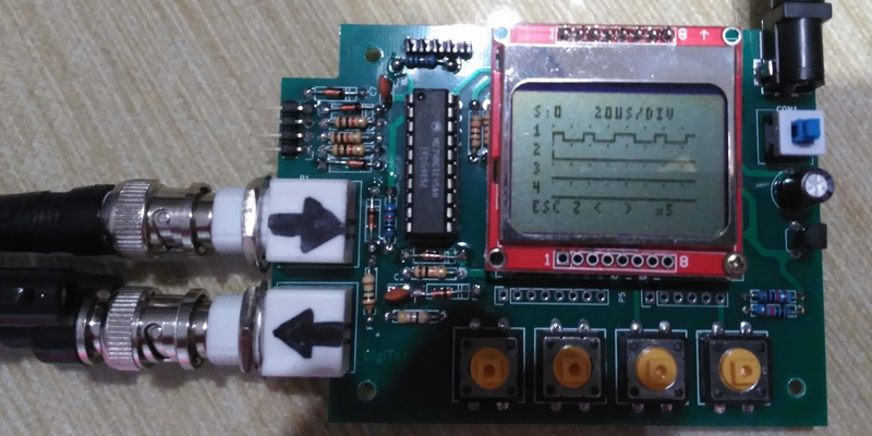
Logic analyzers used to be large boxes full of high-speed logic and a display monitor. Today, they are more likely to be a small box with a USB port that feeds data to a PC application. [Juan Antonio Rubia Mena] wanted something more self-contained, so he built Digitool. Built around a PIC18F2525, the device can measure frequency up to 10 MHz and inject square waves up to 1 MHz into the circuit under test. Oh yeah. It also has a simple four-channel logic analyzer that displays on a tiny LCD.
The 500,000 sample per second rate and the 1024 sample buffer isn’t going to put any logic analyzer vendors out of business, but it is still enough to help you figure out why that SPI or I2C logic is messed up. It looks like a fun project that could have some usefulness.
[Juan] provides all the design files in his post. He also notes that he had to reduce the speed on the CPU to accommodate the LCD. He has the CPU running at 5 V because the 5 V part has a higher frequency rating and he hopes to get the speed to 40 MHz which would, presumably, increase the sampling rate for the logic analyzer.
If you want something more serious, an FPGA is the way to go. Even a cheap FPGA board can easily do many more channels at 96 million samples per second. Then again, unlike Digitool, you’ll need a PC to display the results.


Wow, a whopping 10 Mhz? If I ever get my original IBM PC off the shelf and need to do any debugging that’s the tool with room to spare!
Don’t be such a dick, 10MHz is still more than enough for low speed and hobbyist designs.
Let’s agree to disagree. It’s only good for the kiddie pool – aka “a toy”. Also, bandwidth is useless if you can’t see what you are trying to catch – things stopped being about some rising edge long ago, these days it’s about the 99th byte in some message or the ACK that may or may not follow it – good luck wading through all the edges in-between. An 1080p monitor is barely adequate, a tiny LCD that isn’t even QVGA just underlines the bad joke.
no need for fpga, you can do it with ARM micro (LPC4370 )
http://www.embeddedartists.com/products/app/labtool.php
LPC-Link 2 + labtool add-on =
-11 channel logic analyzer (up to 100Msamples per second)
-2 channel oscilloscope (up to 60 Msamples per second, 6MHz BW)
-11 channel digital signal generator (up to 80 Msamples per second)
Yeah I have one. The problem is you can’t do it all at once. You trade channels, bandwidth, etc. Still nice. Not self contained like this one either unless you add custom.
Something I’m still looking for is a small self contained protocol decoder … Give it a protocol and rate, and have it spit out what’s being sent
I started something like that using an lpc1768, than getting ahead of my self I added complex trigger leveling, outputs, even a small fpga … It all got too much and it was shelved early on
I really should take another shot at it
“If you want something more serious, an FPGA is the way to go. Even a cheap FPGA board can easily do many more channels at 96 million samples per second. Then again, unlike Digitool, you’ll need a PC to display the results.”
Why? Parts are cheap these days. Why not build a Digitool-like device using an FPGA connected to a microcontroller.
Of course a data port for optionally connecting it to a PC would still be an obvious feature even with such a setup.
Great tool! Projects like this are always inspiring.
Agreed. The 84×48 graphical lcd (nokia 3310) refresh rate is the bottleneck (per article AND website info). Even if he had a hobby FPGA (iceLattice)…
My only gripe. Is “PIC Oscilloscope” actually comes back with quite a few hits. One from 7 years ago: https://www.youtube.com/watch?v=gIp4v8wlubQ
Granted this one is at 10Mhz vs 1Mhz and doesn’t require a PC.
I would be really nice for folks to start tearing apart old USB2 peripherals hubs and re-purposing the old Cypress LX2LP chips and some of those cheap mini mp4 players.