There are few greater follies in the world of electronics than that of an electronic engineering student who has just discovered the world of hi-fi audio. I was once that electronic engineering student and here follows a tale of one of my follies. One that incidentally taught me a lot about my craft, and I am thankful to say at least did not cost me much money.
It must have been some time in the winter of 1991/92, and being immersed in student radio and sound-and-light I was party to an intense hi-fi arms race among the similarly afflicted. Some of my friends had rich parents or jobs on the side and could thus afford shiny amplifiers and the like, but I had neither of those and an elderly Mini to support. My only option therefore was to get creative and build my own. And since the ultimate object of audio desire a quarter century ago was a valve (tube) amp, that was what I decided to tackle.
Nowadays, building a valve amp is a surprisingly straightforward process, as there are many online suppliers who will sell you a kit of parts from the other side of the world. Transformer manufacturers produce readily available products for your HT supply and your audio output matching, so to a certain extent your choice of amp is simply a case of picking your preferred circuit and assembling it. Back then however the world of electronics had extricated itself from the world of valves a couple of decades earlier, so getting your hands on the components was something of a challenge. I cut out the power supply by using a scrap Dymar Electronics instrument enclosure which had built-in HT and heater rails ready to go, but the choice of transformers and high-voltage capacitors was something of a challenge.
Pulling the amplifier out of storage in 2017, I’m going in blind. I remember roughly what I did, but the details have been obscured by decades of other concerns. So in an odd meeting with my barely-adult self, it’s time to take a look at what I made. Where did I get it right, and just how badly did I get it wrong?
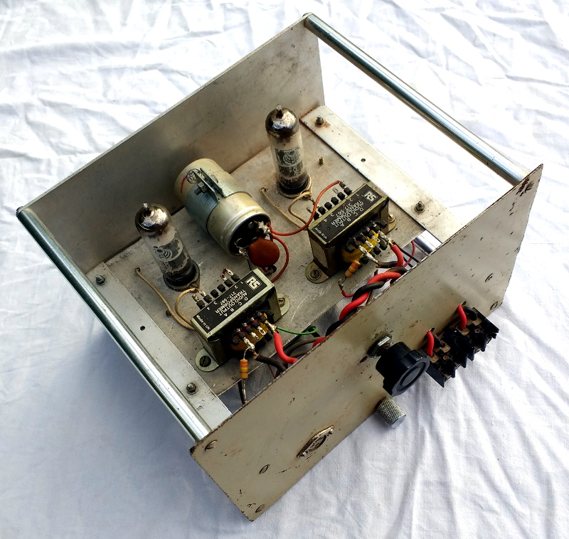
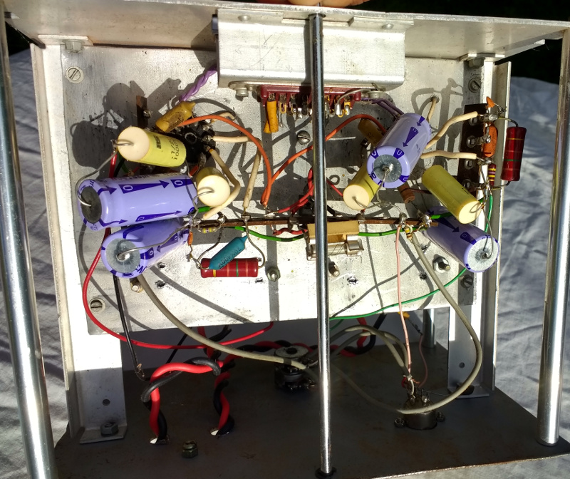
The amp itself sits in the removable portion of the Dymar chassis, I can’t remember what the dead instrument was, but Dymar produced a range of instruments as modules for a backplane. The front panel is a piece of sheet steel I cut myself, and is still painted in British Leyland Champagne Beige, the colour of that elderly Mini. It has a volume control, a DIN input socket which must have seemed cool to only me in 1992, and a Post Office Telephones terminal block for the speakers. Inside the chassis the amp is mounted on a piece of aluminium sheet, on top a pair of PCL86 triode/pentode valves, a pair of output transformers and a supply smoothing capacitor, and underneath all the smaller components on tag strips. Though I say it myself, it’s a tidier job than I remember.
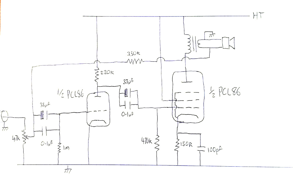
The circuit is simple enough, a single-ended Class A audio amplifier that I lifted along with the PCL86 and the original output transformers, from a commonly available (at the time) scrap ITT TV set. These triode/pentodes were the integrated amplifier device of their day, as ubiquitous as an LM386 in later decades, containing a triode as preamplifier and a power output pentode, and capable of delivering a few watts of audio at reasonable quality with very few external components. They were also dirt cheap, the “P” signifying a 300mA series heater chain as used in TV sets that was considerably less desirable than the “E” versions which had the standard 6.3V heaters. Not a problem for me, as the Dymar PSU had a 12V rail that could happily give almost the 300mA each to a couple of PCL86s.
My choice of parts must have been limited to those my university’s RS trade counter had in stock that had the required working voltage, and are a mixed bag that you wouldn’t remotely class as audio grade. There are a couple of enormous 450V 33μF electrolytics, and 250VAC Class Y 0.1μF polymer capacitors intended for use in power supply filters. I seem to have followed the idea of using a small and a large capacitor in parallel, probably for some youthful hi-fi mumbo-jumbo idea about frequency response. Otherwise the resistors look like carbon film components, something that probably made more sense to me in the early 1990s than it does now.
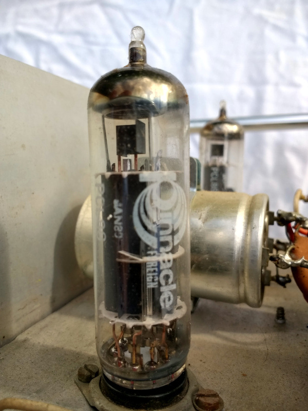
On top of the chassis, the original transformers taken from scrap TV sets turned out to be of such low quality that they tended to “sing” at any kind of volume, so I shelled out on a pair of the only valve audio output transformers I could find at the time, something that must have been a relic of a bygone era in the RS catalogue. The original valves were a pair of PCL86s from old TVs, but I replaced them with a “matched” pair of brand new PCL86s. I remember these cost me 50p (about 90¢ in ’92) each at a radio rally, and were made in Yugoslavia with a date code of January 1980. The new valves didn’t make any difference, but they made me feel better.
How did this amplifier perform, and what did I learn from it?
In the first instance, it performed 110%, because I had a valve amp and nobody else did. The air of mystique surrounding this rarest of audio devices neatly sidestepped the fact that it wasn’t the best of valve amps, but that didn’t matter. Being a class A amplifier with new components, it came to the party with the lowest theoretical distortion it could have had due to its circuit topology. Another area of shameless bragging rights for my younger self, but in reality all it meant was that it got hot.
The sound at first power-on was crisp and sibilant, but with an obvious frequency response problem, it was bass-to-mid heavy, and not in a good way. Here was my first learning opportunity, I had just received an object lesson in real audio transformers not behaving like theoretical audio transformers. It had an impressive impulse response though, square waves came through it beautifully square on my battered old ‘scope.
I could only go so far listening to a hi-fi that might have been a little fi but certainly wasn’t hi. My attention turned to that frequency response problem, and since we’d just been through the series of lectures that dealt with negative feedback I considered myself an expert in such matters who could fix it with ease. I cured the frequency response hump with a feedback resistor from output to input, playing around with values until I lit upon 330K as about right.
The Best Stereo Valve Amp In The World. Yeah, right.
Here was my second learning experience. I’d made a pretty reasonable amplifier as it happens, and it sounded rather good through my junk-shop Wharfedale Linton speakers with cheap Maplin bass drivers. I could indulge my then-held taste in tedious rock music, and pretend that I’d reached a state of hi-fi Higher Being. But of course, I hadn’t. I’d got my flat frequency response, but I’d shot my phase response to hell, and thus my impulse response had all the timing of a British Rail local stopping service. The ‘scope showed square waves would eventually get there, but oh boy did they take their time. The sound had an indefinable wooliness to it, it was clear as a bell but the sibilance had gone. I came away knowing more about the complex and unexpected effects of audio circuitry than I ever expected to, and with an amp that still had some bragging rights, but not as the audio genius I had hoped I might be.
The amplifier saw me through my days as a student, and into my first couple of years in the wider world. Eventually the capacitor failed in the Dymar PSU, and I bought a Cambridge Audio amp that has served me ever since. The valve amp has sat forlornly on the shelf, a reminder of a past glory that maybe one day I’ll resuscitate. Perhaps I’ll give it a DSP board programmed to cure its faults. Fortunately I have other projects from my student days that have better stood the test of time.
So. There’s my youthful folly, and what I learned from it. How about you, are there any projects from your past that seemed a much better idea at the time than they do now?


so what did it sound like when you turned it up all the way to 11? warm tones?
Louder. It didn’t push into nasty-sounding distortion, though I’m sure that was by an accident of relative levels rather than design.
Yes, tube pairs, matched, provide better fidelity than solid state. That’s what they tell me. My ears at age 80 don’t tell me what an oscilloscope shows. But that’s another story. Thanks for sharing this.
Back during my ancient air force days, probably 1963 in the West Indies, a British Lancaster came visiting. The crew chief and the radio operator came to our comm/navigation maintainer shop looking for a valve checker. We sent them to the engine shop. A half-hour later they returned asking for the tube checker.
That’s Gold ;-)
Matched pairs would only apply in a push pull amp not single ended as this is.
I never could see anything on a scope that wasn’t sticking out in a sonic context.
A quality signal tracer amp and speaker is far more useful here.
Fire-bottles!
Scopes are only as good as the operator.
My electronics instructor had a similar story, only this time it was an English colonel yelling at him (a sergeant) that he needed a valve. He started yelling at him threatening to report him for insubordination because they were trying to send him to the engine shop. It was heated exchange (one-sided) until an American colonel walked in and settled things down.
My instructor said he learned 2 things that day: ask for specifics so you can get them the right thing–don’t assume you know what they want, and a college degree doesn’t mean an officer is intelligent.
The Englishman had evidently had a very bad day and this was the last straw.
I’m impressed. Full of new components, the two screws in the valve and socket photo seem to be the same size and one of them even has a washer – classy. I could rarely attain such high standards using my collection of assorted bits from dismantled equipment.
I just probably had more equipment to dismantle at the time :)
“under the hood, and it’s all a bit messy” is that hacker speak for, back in 92 DIY circuit boards were a really big deal?
Nah we had circuit boards in 1992, possibly drawn on paper using a plotter or dot-matrix printer, then UV-exposed and etched. Or possibly using Letraset’s stuff for components. But it’s traditional to build valve circuits on tag-board, or using open-air construction. That goes back to the days when PCBs really were a big deal. I dunno why the tradition’s held. Possibly for inaudible audio voodoo reasons.
Inaudible audio voodoo for sure. They still do this with guitar amplifiers, usually for big money. I don’t often hear the difference, and I build the damn things.
We did circuit boards, as spotty young EE students. Crepe paper tape on acetate, and ferric chloride. Trust me, CAD and a Chinese board house is magic.
Copy your schematic from Popular Electronics or Electronics Now onto overhead transparency sheets on the super-dark setting and use mom’s iron to transfer the toner onto a piece of copper clad. Run the board through a ferric chloride bath and BOOM a usable (though not always pretty) board!
Of course, supplies and the risk of mom’s wrath for using her iron made it a pretty big deal for us poor kids in high school and college.
And acetate melted onto the iron imparted a skanky flavor to any toasted cheese sandwiches you tried to make with it afterwards!
I love how many tube amp articles are being submitted on Hackaday!
There’s just *something* about tubes that makes them sound so much better than transistors, at least to my ears. The issue is that even if you do build an audio amplifier circuit in your EE class, you’re still woefully unprepared to design audio. My first few months in DIYaudio were almost like learning a foreign language, what with all the acronyms and jargon, but it’s an incredibly interesting world.
It’s distortion.
Awesome work!
I am slightly confused about your comments regarding frequency response. When you describe the square wave output as good this should mean the frequency response of your amplifier was quite flat. I guess you measured the square wave voltage output of the amplifier not into a loud speaker load. The loud speaker load is a usually looks like a series LCR with resonance in the mid bass range, something like:
https://www.maximintegrated.com/en/images/appnotes/3879/3879Fig06.gif
So assuming your amplifier had a large output impedance with respect to the load this would result in a greater voltage been applied to the speaker (which has been designed for constant voltage drive) at high frequencies (sibilance) and at resonance (bass boom). By adding negative feedback the output impedance of the amplifier should be reduced.
When you added negative feedback and stated the square wave response took a long time to settle this is the result of instability. From the description of your feedback it sounds like dominant poll compensation (common in audio amplifiers). It may be that you just need to move the poll down in frequency to get good stability, this is usually accomplished by increasing the size of the capacitance that is providing this dominant poll. SPICE models of your valves are available I would recommend some fiddling in simulation land!
We had SPICE in ’92. It ran on the university’s VAX, and I/O was all via text files. :)
IIRC it had a good frequency response when measured using a sine wave, but the phase response was all shot. In other words the phase shift varied with frequency. Also IIRC it was measured into a pure resistive load. And it was 25 years ago, so there’s a lot of IIRC about this project.
We had SPICE in the ’70s, and I/O was all via punch cards. And that’s why the first line is still called the title card. :-)
The text version did ASCII graphs. It would be wishful thinking of me to want the punched card version to punch graphs as holes in card.
By ‘frequency’ response do you mean the magnitude of the (complex) frequency response as opposed to the phase? Because you talk about ‘frequency response’ and ‘phase response’ as if they are two separate things.
Yes lazy shorthand. From a listening prospective only the magnitude response of the final loudspeaker+amplifier system should matter (as the human ear is insensitive to absolute phase). But when adding negative feedback to the amplifier the phase shift of the amplifier is important as too great phase shift and the negative feedback becomes positive and the amplifier becomes unstable.
Because the same transformer is used for both output drive and feedback, the inductive characteristics of the speaker is also coupling back as negative feedback.
If a separate transformer was used for feedback then the characteristics would be more as you described – lower output impedance and less phase distortion.
A Zobel network may have helped but amp design is often a compromise between phase distortion and frequency/amplitude distortion.
Overall this design is very good but unfortunately the output quality is very dependent in the output transformer / speaker coupling characteristics.
In that era designing a good linear bench power supply and an audio amp was more or less a right of passage for upcoming engineers. I designed a transistor amp but now in hindsight it would have been far more interesting to have designed a valve amp. I did however make a linear amp for my 27MHz CB radio out of old scrap valve equipment and that was quite educational.
Seeing the old tag strip give me a warm feeling.
+10 Jenny List
As drawn, your amplifier has positive feedback. Adding polarity dots to the transformer graphic would solve that problem, assuming the amplifier actually had negative feedback.
Also, the feedback varies with the volume control setting. Not necessarily a problem, but not a usual design technique.
The parallel capacitors are unnecessary for the high impedances here.
The lack of a decoupled cathode resistor in the triode stage is bad design technique, I’m not familiar with the particular tube, but it may be OK in your case.
A feedback loop around an audio output transformer of unknown characteristics is always risky, but since you tried it and it worked, and you apparently had a good stability margin, no real problem exists.
Wow, first valve amp design from rookie EE student with yet-to-be-deflated ego turns out to have faults, who’da thought it!
In short, yes. But the piece is about my journey of audio self discovery, not the purity of my design.
Get it perfect the first time, or don’t bother trying! Sheesh! ;-)
how come people cant take honest criticism any more?
people are taking time and energy to formulate issues that YOU can then improve on, or not(your choice), people should thank them!
there were no insults in the OP, only quite well contextualized issues, none were described as entirely wrong and there were caveats against his own points, what more do you want?
Your post is missing capital letters everywhere except where used for emphasis, and for abbreviation.
Also, it is missing an apostrophe it very obviously needs in line 1; “can’t” is a different word from “cant.” Might be obvious from context, but still not correct.
If you are using parentheses to add a couple of words on a tangent to your sentence, there should be a space before the opening parenthesis.
In spite of the last sentence of the post being a run-on, you are still missing some kind of punctuation after the words “entirely wrong.” I would actually space that out into an entire new sentence, rather than continuing the run-on. To be honest, the last sentence should actually be about three sentences.
Are you going to thank me? I gave you honest criticism you didn’t even ASK for!
Let this post bring you enlightenment.
Jenny, this is a success; not a failure. You built it, it worked, and you learned a lot! That makes it a 3-hit winner!
You do you, tube people, but at this point if I want the “warm” distortion tubes introduce, it’s pretty easy to add that digitally. I’d much rather have solid state electronics that can sound like tubes *or* like the music, movies, and whatever else was actually intended to sound when it was mixed.
Having found Peace and equaliser APO on windows I agree that a decent EQ is all you need. However I can’t deny the appeal of ever-so-slightly glowing vacuum tubes. What I’d love to replicate are the mainframes from Fallout 3 where the entire front glows red under load.
I have LED Matrices I am putting in front of my file server… needs bondo i guess for the curves.
Please note: every other piece of audio kit I’ve owned or built since has used transistors.
I can remember when people couldn’t wait to build, or buy, a working transistorised anything .
That remembers me of my HF-engineering professor at the university:” I take a tube if I need kW of HF power. If I need just a nonlinear voltage response, I take some OpAmps.” This was in the 90ies, so DSPs were not as advanced as today.
And he owned a short wave amplifier where one tube made 2kW of HF power. The PSU was also as big as a beer-bottle box and had a 3-phase transformer good for up to 6kW at 3kV. It was told, that he was known as the loudest – and cleanest – non-club amateur radio station from Europe for some time :-)
AFAIK this amp and PSU were from some eastern Europe or Russian military surplus gear which he completely refurbished.
It doesn’t matter how this amplifier “sounds” or even how it tests using the best test equipment available… It will “sound” MUCH better if it costs $10,000! And don’t forget the $1,000 “Gold” Litz cables to connect it up.
Silly wre was beyond my budget. So I used 60A cooker flex as used in thousands of British kitchens. And kidded myself that it would make this weedy little amp sound better. It didn’t.
If you look, you’ll see thick twisted pairs of switchgear cable from the little transformers to the similarly meaty speaker terminals. Effect? See previous paragraph.
I think a lot of hifi enthusiasts would be horrified at the equipment that most bands use, at least when they’re first starting out.
Certainly no £1000 amps or gold-plated cables.
The equipment live performance musicians use (i.e., “Bands”) is the exact opposite of what Audiophiles seek. For example, a guitarist seeks DiStOrTiOn more than Linearity. An Audiophile strives for Linearity. All the knobs on a guitar amplifier are to there to allow the user to control distortion and feedback.
The problem is there are “Audiphile$” who do not understand the effect of distortion on how it affects the proven Psycho-acoustic model of Human audible perception – they only understand Money Equals Better Sound; and “Audiophiles” who do understand what the limits of linearity are when it comes to Human listening – regardless of price.
Admittedly; however, attention to one more non-trivial detail is in order, por favor —
If she were going for a $10 000 amp, the front panel should have been painted British Racing Green, and most definitely not British Leyland Champagne Beige. How gauche! A true money-is-no-object audiophile purist would demand no less, no less. And it IS a very good amplifier; it simply needs a splash of BRG to say so to the world.
Solid state amps typically introduce more distortion than well designed valve gear. I am unsure where this hard felt belief that solid state offers less distortion/more accurate reproduction has come from.
http://spectrum.ieee.org/consumer-electronics/audiovideo/the-cool-sound-of-tubes/distortion
Whether this advantage and lower overall efficiency is worth it for audio is another matter though.
this is literally the only place i have ever heard of this, have any other sources?
Very interesting read. Thanks for the link.
I am a little disappointing that the sample rate was only 20-bit 48ks/s when the highest tested harmonic was 10kHz but it still looks legit given the FFT analysis. We used to do N&D (Noise and Distortion) testing with triple T notch filters.
I hardly remember the valve theory now about selecting the other components to suite a tube like bias and tuned networks for Pentodes etc.
i would be careful, the writer and experimenter is the owner of a tube company, the methodology is also basic, which he admitted himself, hence why i asked for other sources.
I had to do the same testing / experimenting in my original EE, obviously a long time ago.
Distortion was not a big issue with valves, it was more about getting a linear voltage output for a given liner voltage input. Frequency distortion is more about coupling transformers.
I always new that transistors have junction noise because they actually have a junction and when a stray electron pops across, it creates noise. Valves on the other hand work on averages due to the plate distances and when an extra electron pops off (perhaps due to a photon) then it is most probable that it will simply be re-absorbed before it can cross the plate distances.
It’s good to see a comparison with transistors though.
At the same time these tests aren’t definitive to a transistor or valve amp as they are only the active component and don’t include stage coupling or feedback.
None the less it makes a very interesting read.
“…Are there any projects from your past that seemed a much better idea at the time than they do now?…
Actually, a 1972 project that seems a much better project now than it did then: a one-IC clock using six V-F display tubes. One chip. Green ‘nixies’. Caps, resistors, diodes, transformer(s).
All this current hard work and thrashing around designing and building clocks, and the fascination of using “nixies” has left me ‘cold’, as I remembered having designed this (with the help of a mfr’s app note), laying out the pcb, and its working the first time it was turned on.
After three house-moves, I found it two months ago in the basement, lurking on top of an old fridge, and decided to see if ‘the old ways’ had any validity. Took it down, plugged it in (It has no on-off switch. Why do that? There is a fuse).
Worked the very first time. Again . Nary a line of code ANYWHERE, and it’s been keeping excellent time. But of course; there’s no microprocessor involved.
“My favorite programming language is solder.”–Bob Pease.
Please write it up somewhere and submit it to the tips line. Really.
Thank you for your implied confidence; I may just do it.
What I’d really like to do is use a RPi to build a clock. Is this a dumb idea (forgetting any idea of cost-effectiveness)?
If you make it, it’s not a silly idea. In that many of the things we feature are frivolous as things, but contain interesting tech or builds. Doesn’t make them any less valid.
Yes, please, send it in. I have a few single-digit VFD tubes robbed from a calculator needing to be used.
Seems as though an article on using V-Fs is more in order. Affordable (yours were free) V-F displays are more prevalent than clock chips, which can cost upwards of $70. Which is why all the clocks are now designed with code…
Certainly better than my PL504 CW transmitter design, whose function I could not test since I had no SW receiver :) Ah the bad old days.
After I finally obtained a receiver, I instructed my brother to key the TX on/off using a Morse key while I went out to see the TX range. While I was climbing the nearby hill, the signal disappeared. Try fiddling with the knobs, nothing. Only when I got back to the house I have found the reason: my brother got bored with the Morse key so he placed a book on it to send the signal all the time.
Constant ON CW signal was very hard to discern with that receiver, with the usual SW heterodynes.
I had a mind to use PL504s in an audio amp at the time. Ran out of steam though.
That a really special moment coming face to face with your younger self through something you have hand crafted.
Sometimes it scares me when I look at old projects and think my God how did I survive!
something about those 33uf caps does not look right to me. the feedback wire from the input to the speaker also looks wrong. my hunch is it and the 33uf caps are causing the extra bass.
Not so. There is a whole barrel load of wrong in that design as I have outlined, but the “hump” was there with just the 0.1uF ones too IIRC. ISTR trying all sorts at the time.
The engineer’s First Law should be, “Does it work?” If it does, then leave it alone–hardware AND software.
Looks like a great design to me (as Count Basie said when asked about what constituted good music, he said, “If it sounds good, it is good.”). The only “meatball surgery” I’d make–if it were mine, and it’d been resurrected after all these years–would be to change the pentode’s cathode resistor bypass cap to something like a 0.01 to 0.1 microfarad ceramic. Only if it were mine. Not someone else’s baby. Good job…
“…the 33uf caps are causing the extra bass.” Weelll, yeah, but only because they’re providing a good, low-impedance path down to 0 Hz… They’re not causing the extra bass; they’re the reason for ANY bass.
”
The Doc says:
Solid state amps typically introduce more distortion than well designed valve gear. I am unsure where this hard felt belief that solid state offers less distortion/more accurate reproduction has come from.”
That “hard felt belief” is absolutely true, and it comes from accurate measurements performed by competent engineers. Properly designed solid-state amps measure better in every way then the best that tube designs can offer. Plus solid state offers vastly superior reliability.
What some tube amplifiers *may* have, is “euphonic distortion”; subtle alterations to the signal that make it less accurate, but producing a sound preferred by some people.
Yes. Plus, all tubes are not equal: triodes and pentodes differ greatly in their distortion characteristics.
Pentodes have a much more linear gain characteristic than triodes.
If distortion is needed for ‘warmth’, use a triode. Then, when you’ve introduced all the warmth you can stand in the pre-amp stage(s), do your ‘business’ amplification with transistors, or pentodes.
I looked at the schematic only now, after posting the preceding. I’d like to add,
“…just as Jenny has done…”.
For me, it was 1965 building a single-tubed superheterodyne shortwave receiver using a 12AT6(?). It worked really well through a long wire antenna hung up in my bedroom in Toronto – over the window wall for north/south and over the door for east/west. The chassis was an actual Hammond chassis but drilled out and filed to suit – I was not (still am not) a neat machinist.
Before that I had adjusted the intermediate stage coupling coils in a discarded AM radio to tune in shortwave. I never knew what frequency i was listening to but I knew that I was a little or a lot above or below CHU or WWV. I learned morse code that way but it’s long forgotten as I didn’t carry on with ham radio.
I have a trailer full of old projects that were great back then (20-25 years ago) but now looking back were terrible wastes of time and money, half of them being the “Well, I’ve invested this much time and money, might as well see it through” types of projects. Probably the worst was the $100 tube amp with switching power supply that I spent close to $300 to get up and running only to have my ears assaulted by scratchy, squeaky sound. Looking at it now, I know that there’s a good reason that capacitors have temperature ratings.
Or, maybe it was the Jacob’s ladder supply made from a capacitor, Quadrac, and ignition coil packed into an ungrounded metal box?
to make an amp yourself and to make it sound really nice is great thing. i am bit jealous, really.
I love it!!!! I think what makes tubes very attractive is that it’s made of glass and if you could see electrons, this would be the best way. There’s no magic smoke hidden in silicon layers.
Cheers,
Josh Bensadon
Toronto
The best stereo valve amp in the world ….. is still outperformed by the average Solid State Amplifier
“Warmth = Low pass filtered distortion products …… Great for amplifiying otherwise boring sine waves from an electric guitar
I will now take a defensive posture against the Audio Trolls wielding oxygen free cables ……
Sorry some of the best amps produced are tube amp hands down IMO. Audio Research, McIntosh and many more are still produced today. The largest one I know of is rated at 750 watts by Audio Research. You just won’t find them at Best Buy or Walmart.
Paralleling a smaller cap with an electrolytic wasn’t “youthful hi-fi mumbo-jumbo”, it was a sound, (no pun intended), practice. Electrolytic capacitors have known, measurable deficiencies that can create audible artifacts, and bypassing them with a good-quality film capacitor may improve the sound somewhat, especially at higher frequencies. Hundred-dollar capacitors in the ‘audio jewelery’ class of components are mostly snake oil for suckers; but a good, well-made film capacitor can beat the pants off any same-value electrolytic, at least in some parts of the circuit in some systems. On a slghtly different note, (again, no pun intended), there’s a good reason for (some) tube amplifiers to sound much better than (most) solid-state amps – check out Lynn Olson’s “The Sound of the Machine – The Hidden Harmonics behind THD” at nutshellhifi.com.
You are absolutely correct; and it is still a very good practice because electrolytics have thoroughly terrible–large– higher-frquency impedance. “They’re pretty good caps at DC, but not too good at 1 KHz””, as a friend used to say.
We can say what we want about tubes or trans ,and I like both
Good solid state stuff is hard to beat,I hear a difference in voices on tubes
And sounds very different to my Martin Logan speakers
I own both in my home and think it’s very cool to build tube amps
This amplifier was extensively used in small record players in the 60s and early 70s. I had one of those (mono) and made it a stereo by adding a second amplifier inside the box, where the original 6×7 speaker was. The sound was really poor, even with good speaker boxes. It got better when I changed the trafos, got two matched tubes, and added a Baxandall pre implemented with two 12AX7s. Of course, I had to get a larger ac trafo and filter, which forced me to get a new cabinet. It was a great learning experience, but far from successful in terms of audio quality.
Yes, this was ‘entry level’ in the ’70. With a pair of 8 inch philips speakers with 22 liter closed baffle it was a low cost acceptable option. But not this circuit. The right capacitors in the gate coupling, the right cathode resistors and NO negative feedback. I used to make them with horizontal tubes, so they had the compact look of the ‘solid state’.
I could talk of some of the crap you talk and your other commenters talk…the typical audio types…however what is most appalling is the quality of your construction…even an experimental model built by anyone with pride in his work and common-sense and an element of “EE” science would be ashamed to produce such a ghastly way below amateurish arrangement. To then publish it in your ‘look at me…look at me’ appeal .
The circuit itself is bizarre…that’s ok if learning from it, however you should appreciate that perhaps million of amplifier circuits which have engineering science in them have been produced already and yours adds nothing to them other than ‘what the!!!”
This plagiarised b/s is an effort to appear knowledgeable even expert but you obviously are not…why not get educated first then start designing sensibly, rather than embarrass yourself (other than like-types).
Your plagiarised segments:….and what utter lahdedah irrelevant waffle some of it
“These triode/pentodes were the integrated amplifier device of their day, as ubiquitous as an LM386 in later decades, containing a triode as preamplifier and a power output pentode, and capable of delivering a few watts of audio at reasonable quality with very few external components. They were also dirt cheap, the “P” signifying a 300mA series heater chain as used in TV sets that was considerably less desirable than the “E” versions which had the standard 6.3V heaters. Not a problem for me, as the Dymar PSU had a 12V rail that could happily give almost the 300mA each to a couple of PCL86s”
From Experimental Methods in RF Design (Hayward, Campbell and Larkin):
“Ugly construction… the scheme works well and continues as a recommended method.”
“The greatest virtue of the ugly method is low inductance grounding.”
“We have never had a problem with ugly equipment being lest that robust.”
“’Nice looking’ circuit construction does not always equate to good circuit performance”
“It’s not about craftsmanship. A portion of the homebrewing community was schooled with the idea that “nice looking” circuit construction went along with good performance. But the two factors are generally isolated.”
And so on.
Well everyone starts somewhere and yeah if there is one electronics death-trap it is the DIY Audio type. <.<
I kind of fell for it. It is fun, but oof can it be a folly at times. I spent the first half year just trying to discern Fact from Myths cause OH BOY are there many! @.@
On youthful projects that are shamefull. My first completed project: a USB-Powered IV-9 miniature Numitron clock would be that. Definitely on my list to make a "Proper" version off. The mistakes it had:
-Silly size capacitors for an USB device. Also using Elektro-caps while i didn't need it cause i did not know 10uf ceramic blocks existed…
-Put a thermometer close to a LDO without physical isolation. Yeah that one didn't so much measure the room-temp i had hoped as it measured how hot the PCB near the LDO got…
-Speaking of which. Used a linear regulator that was prone to getting hot.
-Used 74HC595 to sink the numitrons. Pushing them well over their current ratings cause i once read one can. they survived, but yeah just improper.
-Relied on an uncompensated clock crystal which due to regulator heat was drifting a lot. Who needs precision…. <.<
-Lastly. I lost the MCU's code about one week afterwards… So it would do some old stupid behaviour.
Still think it was clever though that i used a regulator for regulating the 5V down to 3V. Letting me avoid having to use resistors to keep the filaments from burning through
Late to the party here, but as a student I too, through lack of funding, built my own stereo amplifier to impress, and distress, my hall neighbours.
It worked adequately and didn’t get too hot – largely because it had no case and was just an open chassis.
The caselessness motiff extended to my speakers too, which, for testing, were laid on their backs on either side of the amp.
A few minutes into a max volume test came an earsplitting crack followed by silence, and, as it happens, darkness. The old building I had a room in had the old round pin sockets which only had central fusing.
Once the lights came back on I could see the problem. The speakers had both moved considerably due to the virbrations renedered by “The Passenger” (Yes I still recall the song) and one had wandered across the table to make contact with the amp and create a short.
Wonderful. Still, not a 100% fail. Just a 50% fail. Only one channel had blown. So it was a Mono Amp – which I stuck in a box soon as – with which I saw out my uni days.
Thanks for reviving those memories Jenny.
“or gold-plated cables.”
And let’s not forget the low O2 copper wire….
We ALL know that makes it sound better :)
Haha, that’s awesome! You built it, it worked, and you can’t learn any better way. I did my HND in Electronics and Computing in about 1984 at Luton. Final year project was an 8 bit digital delay based on 64k of scrap DRam I got from somewhere and lots of TTL logic. Digital stuff was wire wrapped. It kinda worked but sounded like a bunch of psychotic daleks on cocaine. Don’t think I ever used it but I learned a ton and it got me a distinction. Only way to do it!
List: Loved reading about your journey, and love a lot of the comments about improving circuits when they take time to leave readable explanations. I’m beginning my amateur journey (decades later than you) to building my first home HF rig and have read the ARRL handbook, the Hayward et al. book and Harris’ Crystal Sets to Sideband e-book many, many times over. The vast majority of information out there describes a “simple circuit” of dozens of mystery components with even more mysterious purposes that was totally impenetrable. I have slowly progressed from utter confusion to (barely) being able to look at a schematic and sort of identify an oscillator block, sort of identify an amplifier block and so on. I will never be able to glance at a schematic and offer the advice that some of the commenters here can amazingly identify off the cuff. Someday soon I’ll actually pick up the iron and dive in- I hope I can make a functioning oscillator as you have made a functioning amplifier and learn what each and every component does along the way. Having a functioning device is barely on my list of priorities since I can just buy a modern awesome transceiver that will do literally everything, and massively better. I’m also happy to be starting this hobby now, where I can get a used digital storage oscilloscope, AWG, tiny SA etc for even less than the cost of said modern digital transceiver. 73- craig