
In a previous article, I discussed LEDs in general and their properties. In this write-up, I want to give some examples of driving LEDs and comparing a few of the most commonly used methods. There is no “one size fits all” but I will try and generalize as much as possible. The idea is to be able to effectively control the brightness of the LED and prolong their life while doing it. An efficient driver can make all the difference if you plan to deploy them for the long-haul. Let’s take a look at the problem and then discuss the solutions.
The Problem of LED brightness control
Most newbies will be interested in making an LED glow without blowing it up. A little further down the line, it comes down to brightness control and then mixing of colors to produce any shade from the color picker. In any case, it is essential to have a clear understanding of the end application. A lighting application such as a work bench light will seldom require a romantic mood light control. On the contrary, a disco light will require fluctuating intensities of various colored LEDs.
So how is brightness perceived? Logically speaking, when you have two LEDs lamps of 100 lumens each, the result should be double the brightness. In reality, human eyes are logarithmically sensitive to intensity change which means that doubling the intensity will be perceived as a small change.
Perception of light intensity follows Stevens’ Power Law with an exponent that depends upon the amount of your field of view occupied by the light. For a 5 degree spot the exponent is about 0.33 but for a point source, it is about 0.5. This means that for a 5-degree spot the source needs to increase by a factor of 8 to seem twice as bright and a point source, needs to increase by a factor of 4 to seem twice as bright.
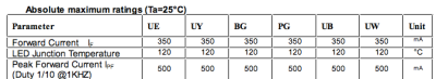 Let us start with a simple 1 W SMD LED like the one available from Adafruit. This one is rated at 90 Lumens and comes with an aluminum PCB as a heat sink. Here is a quick look at some of the parameters of for the LED.
The datasheet has some pretty important information starting with forward current(continuous) and peak forward current. The values are 350 mA and 500 mA respectively and should not be exceeded.
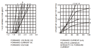
Two more important pieces of information are used which are represented as graphs. The first is the forward current and voltage graph which shows that a voltage of around 1.8 V is enough to forward bias the LED. The current rises ohmically after that and at around 3 V, it is reported to draw around 200 mA. The second curve is the relative LI vs forward current which shows that the current controls the amount of light output (the straight line stretching up to the “4” mark).
Given that the LED follows Ohm’s Law, the current should be directly proportional to the voltage and hence we can vary the voltage to control the brightness. Well, there is just one small hiccup that the curve of the forward current is so steep that a small increment in voltage will have a larger change in current. The brightness will be different if you connect a coin cell as opposed to two alkaline batteries. Both have a 3 V potential difference but the amount of current supplied by either is different and consequently, the brightness is different. Rather than control the voltage, it’s better to control the current passing through the LED directly.
The Simple Approach
The easiest thing to do is add a potentiometer in series with the LED. Simple! Essentially when you vary the resistance, Ohm’s Law kicks in and voila! Variable resistance equals variable current equals variable brightness.
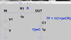
Here is a simulation of an LED with a variable resistor varying from 100 ohms to 1 kilohm. The only problem is that if the resistance of the LED changes or the voltage fluctuates, the result may be devastating. This is essentially an open-loop control and there is no feedback from the circuit to the user other than varying brightness.
Of course, there is also the issue of efficiency since the there will be power dissipated by the potentiometer as well.
Current Control
Next easiest is to create a constant current circuit. There are a number of ways to create a simple constant current source and I highly recommend going through the book, “Art of Electronics” for a detailed explanation of the same. Unsurprisingly there is a Wikipedia article on the subject as well.
You could use a classic LM317 variable voltage regulator to provide a small constant current. It is not very efficient since there is there is a lot of heat dissipated at the adjustment resistor at higher currents.
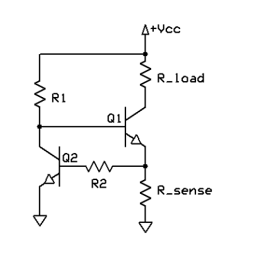 The better method is to use a closed-loop circuit that provides analog feedback to inhibit excessive currents and compensate for variations in the load. The circuit shown is a simple current limiter and is recommended since it offers a higher efficiency than other transistor circuits.
It works to limit the current through R_sense such that the drop across it is no more than 0.6 V. If that happens, Q2 switches ON and Q1 will be switched OFF which limits the current through R_load which in our case will be an LED. Adjusting R_sense using Ohm’s Law we can adjust the maximum current thought our LED.
I personally prefer the above circuit with Q1 replaced with a MOSFET however in cases where we want to control the brightness digitally the next method would be a much better fit.
The Digital Method
The next circuit involves the use of a set of pulses to switch ON and OFF the current through the LED. It’s like flicking the power switch quickly enough that it seems like the light is dimmed. Commonly known as PWM or Pulse Width Modulation, a series of pulses with variable duty cycles or ON and OFF times can be employed for the task.
Under this topic, there are two parts to be discussed. The first is the switching source which can be a simple oscillator or a microcontroller. The second is the switch itself which will be the driving stage of this design. Let us take a look at both in brief.
The PWM source
For generating the pulses, the humble 555 is a good choice. The circuit shows a simple PWM circuit with T1 being the switching element.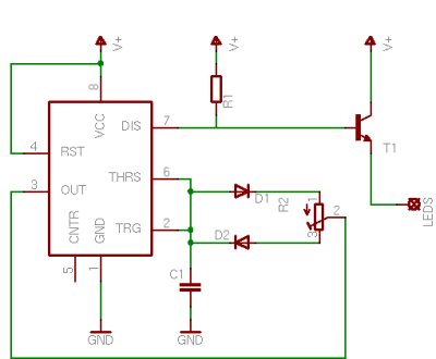
For generating the pulses, the humble 555 is a good choice the circuit below shows a simple PWM circuit with T1 being the switching element.
At this point, we have a number of options and questions to be answered.
1. What is the correct frequency for the PWM?
2. How do I know the amount of current being supplied and
3. How does all this affect the brightness?
The frequency of the PWM effects the flicker perceived. A simple example is when recording digital video if you use NTSC in a 60 Hz lighting environment, your camera will pick up a lot of flicker and switching to PAL will help a lot. For PAL it is 50 Hz so try it out right now with your web cam and see the effect.
The idea is that higher switching frequencies are better but you cannot go arbitrarily high. Remember, all LEDs have a turn-on time which is required for it to switch on and start glowing. If you switch too fast, the LED just won’t turn ON. Another consequence is that the frequency has an effect on the efficiency of the switching element and we will touch on that in a moment. Right now we need to figure out the best frequency for our LED. Scroll back up and check out the last entry in the data sheet snippet.
It says 1 KHz which is what the manufacturer recommends and in most cases this information will be provided in the data sheet itself. If not then anything above 500 Hz should be usable. Check out this link for an application on dimming LEDs.
Since this technique allows for a digital control over the current, ergo the brightness, the next step would be to figure out a way to control the brightness. Remember, the LI is directly proportional to the current but perceived brightness is logarithmic. We need to translate the linear stepping input into a logarithmic current variation.
When using microcontrollers or even FPGAs, the answer is very simple – loookup tables! Have a list of PWM duty cycles that correspond to a sequence of perceived brightness values. A great example I have to mention is here, where the designer uses an FPGA to create a log LUT to generate a linear PLI from user inputs. The same lookup table can be used with an Arduino and I strongly encourage you to try.
Personal Note: When LEDs appeared initially, one of the problems that we faced was that the LED drivers that came with the lamps would malfunction. I initially designed a small circuit to limit the current along with a thermistor to shut down the LED if the switching element overheated. Eventually, dedicated solutions started coming up which we will take a look at in a proceeding sections.
Let’s Switch: MOSFET vs BJT
The second item on the menu is the actual switching element. You can use a BJT or a FET or a MOSFET depending upon your budget and state of mind. BJTs are simpler creatures and require very few additional components. A 2N2222 can safely deal with 800 mA of current which is good for many applications.
MOSFETS, on the other hand, are more demanding in terms of components and require a little bit of care to deploy. In exchange, they offer a far less ON resistance of the order of milliohms and a higher efficiency. Let’s take a look at both.
The BJT LED Driver
![]() Here’s the simplest BJT LED Driver circuit. It consists of a transistor connected in common emitter configuration. The transistor gets switched on when the input switch is closed which allows for current to flow from the LED to the ground terminal. The resistance is calculated as
Here’s the simplest BJT LED Driver circuit. It consists of a transistor connected in common emitter configuration. The transistor gets switched on when the input switch is closed which allows for current to flow from the LED to the ground terminal. The resistance is calculated as
r0 = (Va+Vce) / Ic where Va is early voltage.
This is not constant and varies with the operating point of the transistor and under saturation condition is of the order of a few ohms. The power dissipation is insignificant for a few milliamps but quickly becomes a problem for larger current draws.
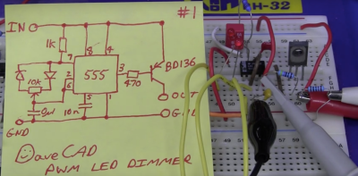
I refer you to a video post by [Dave Jones] of the EEVBlog where he uses a BD136 and a 555 to vary the brightness of LEDs on a piece of equipment. This works for loads with lower wattages however if you are looking to drive larger LEDs then expect to add some pretty hefty heatsinks.
MOSFETs are an LED’s Best Friend
A MOSFET has a very low ON resistance of the order of a few milliohms which means that in such a state, it will dissipate very small amounts of heat as per P = I2R.
Since these are voltage driven devices and have very high input impedances, we can safely parallel together a bunch of them. Unfortunately, these are also susceptible to false turn-on events hence for switching applications, circuits must be carefully designed. A more detailed explanation is available here for the interested however for this writing, we will continue with a general case.
Designing a Lamp
I recently bought two no-brand LED panels from a local hardware shop. The seller told me that I should connect them to a 12 V source and they will work. When I chained them together and connected them to a bench power supply, I found that at 12 volts, they can draw up to 2.7 amps! The brightness is frightening at close range and I need to control their brightness.
 The next step is figuring out the MOSFET that will be the best fit. Considering overshoots while switching, I would like to go for a 20 V or even a 30 V Drain-Source voltage device to be on the safe side. As for the current, if I intend to pass around 5 amps of peak currents, a Res(ON) of 0.1 ohms would mean 2.5 watts! In such a case my heatsink cost would greatly affect my final product. Instead, I would like something with a fraction of the ON resistance- like 0.01 ohms or less, especially for SMD devices.
Next, I intend to switch the MOSFET with either a 555 or an Arduino. This translates to 5 V Vgs and so Logic Level MOSFETs are preferred; though I will be driving the LEDs with a 12 volt supply hence I could use a transistor or dedicated MOSFET driver. Without it, the effective resistance would be higher but it is worth a try none the less.
I am also tempted to look at the PH2520U and the now obsolete MTP3055VL which is a Logic Level MOSFET. The MTP3055VL has a relatively high ON resistance and can be turned on with 5.0 Volts at the expense of 0.18 Ohms and a lot of power dissipated.
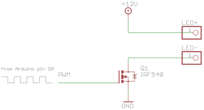
The IRF530, IRF540, IRFZ44N, and AO3400A are all good choices since I have a couple of them in stock. Using an IRFZ44N, I made a simple LED driver and used an Arduino Uno directly. Remember the Arduino pins go up to 5V and I used the fade example that generates PWM out of the box. The frequency of the PWM signal is 490 Hz which is pretty decent.
The result is an effective dimming of the panel. However taking a closer look at the waveform, we see that the output has a significant rise time with a single LED Panel.
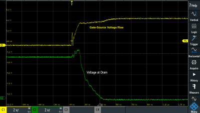
This is due to the capacitive parasitics as well as a weak current drive and can be remedied by adding a transistor driver stage. This TI application report (PDF) documents gate driver circuits pretty well with reference to a non-inverting bipolar totem-pole driver which has been studied in detail by [Joost Yervante Damad]. Since our switching frequency is in the lower range, these switching losses are insignificant. If we were to switch in the kHz range or MHz range, these parasitics would quickly be the death of our prototype.
In my case, I proceeded with no driving stage but then modified the code for 75% duty cycle and measured the current draw with a varying value of PWM. Turns out it sucks up a little short of 1 A of peak current. The MOSFET did not heat to the extent where it would require a heatsink, so the circuit is usable as is for this LED panel as well. I can proceed to make a PCB for my little lamp, however, there is one more option I would like to take a look at.
LED Drivers
 Dedicated LED driver chips enable you to control LEDs effectively without having to think about all the parameters. A good example is the TPS92512 which allows for control of high brightness LEDs using PWM which is internally controlled. Current control is implemented internally and external signals including PWM as well as analog signals can be used to control the brightness linearly. No need for lookup tables.
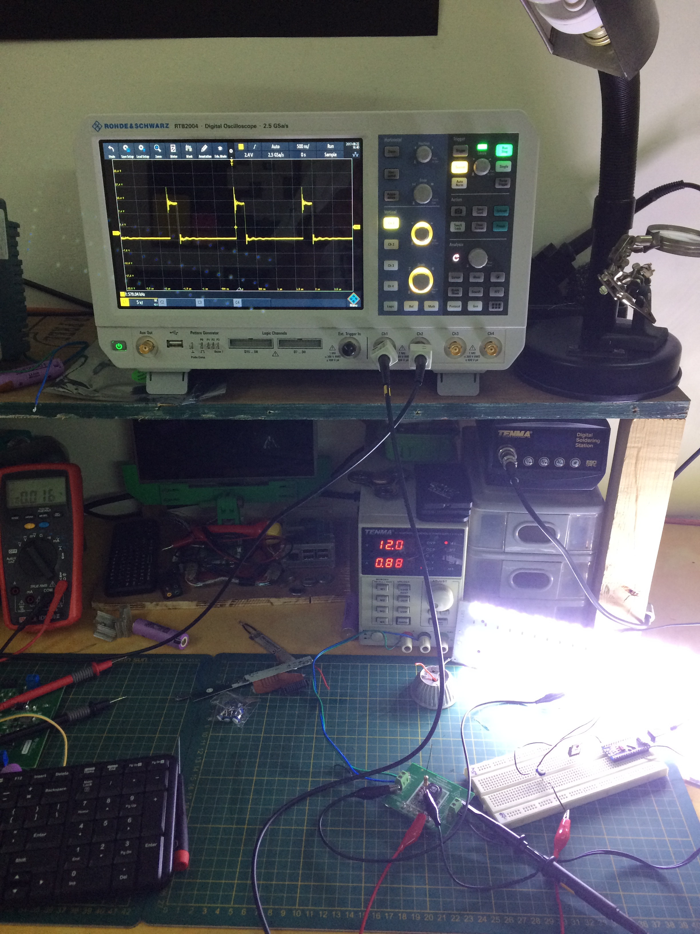
I wired up a test board with the same LED panel such that the brightness is controlled using the IADJ pin. A simple preset was used to vary the voltage between 0.8 and 1.8 volts at the desired pin. The output is a clean and efficient varying voltage which is filtered by an output stage cap.
The PWM frequency is around 580 kHz when probed between the inductor. I could not see any oscillations at the output LED pins though which means the filter stage does the job effectively. I created a DIY version of the PCB in Autodesk Eagle (GitHub) which you can download to make your own.


There is a little OSHPark purple in there and I hope to solder it up myself. Looking at the size of the pins it should be a fun exercise. Let me know if you make one yourself.
Conclusion
So how do you drive an LED? The answer lies in your application area. For small LED current draws, BJTs are simpler and the least expensive. For medium current draws, MOSFETs are a better fit and if you want solutions that offer great out-of-the-box experiences, dedicated driver chips are the way to go. As for me, I have a lamp to finish which will use the middle road since it worked out in my tests. If I ever come to the point where I see flicker in my videos, then the TPS92512 solution will come in pretty handy. I am sure you have a solution of your own and the best way to share it would be a project on Hackaday.io. Go ahead, make a little lamp with light as white as snow and share with us your story.


The forward current(continuous) and peak forward current numeric values are swapped.
it’s also a name https://en.wikipedia.org/wiki/Viola_(given_name)
And an instrument!
(And a typo.)
Both this and the swapped vowels have been fixed. Thanks.
But why twice
”
or generating the pulses, the humble 555 is a good choice. The circuit shows a simple PWM circuit with T1 being the switching element.
For generating the pulses, the humble 555 is a good choice the circuit below shows a simple PWM circuit with T1 being the switching element.
”
?
pretty sure “voila” just means “see there” i.e. from “voir” (to see, to look) and “la” (not sure if this means ‘there’ as in “la bas” meaning ‘down there’, or if this means ‘her/it’ as in female form of “le/la”)
which would render it to mean something like “look [what we have] here”
voilà has NOTHING to do with violate or rape. It is a contraction of voir and là, literally meaning “look there!”.
This information is on the same web-page that you linked — https://en.wiktionary.org/wiki/voil%C3%A0
Most recently, I was dealing with microcontroller control over a multi-digit 7 segment display (for a clock). At first I used a dedicated SPI display driver chip (MAX6951) that both managed the segment current for you and charlieplexed the digits. The downside to it was that it was a very expensive chip. It was actually about half the BOM price to upgrade the controller to a faster one and multiplex the display myself. The microcontroller can’t source or sink enough current, of course, so external switching is required. In this case, I found a pair of chips that are 8x banks of high-side and low-side MOSFETs. Unfortunately, the design gives up charlieplexing, because there isn’t a simple straightforward way to make a charlieplexing current buffer other than a ton of discrete components, but the upgraded controller also has enough pins to spare so that this doesn’t matter. The last challenge is current limiting for the segments, but again, other than using 8 discrete current limiters, there’s no good solution available. The next best thing is to use a constant voltage supply for slightly higher than the continuous Vf of one segment (because the duty cycle for an 8 digit multiplex is 12.5%). The display power comes from a buck converter for good efficiency, and its nimble enough that you don’t see any brightness variations with different digit combinations (an 8 next to a 1 is a challenging transition).
I made 4 brightness levels by making a 320 kHz interrupt source with a timer. Four interrupts are used for brightness levels and there are 8 digits, so the result is a 10 kHz raster rate. This takes up around half of the available CPU time, but what’s left is plenty for the actual application.
One solution for the segment current control problem is to use a segment power supply whose output current depends on the number of segments to be illuminated, perhaps based on an op-amp summing circuit that feeds the reference node of a constant current source/sink. It is a relatively simple task to design a circuit that sinks or sources N*I(seg), where N is the number of segments being illuminated and I(seg) is the desired current per segment. However, series current limiting resistors are usually quite usable if the power supply voltage is at least a couple of volts higher than the LED forward voltage.
The big challenge is balancing the desire for a precision supply against the size and cost of the BOM. Opting for constant voltage instead of constant current has the downside of only really working well with well matched LEDs, but 7 segment displays tend to be well matched anyway.
In the end, it’s probably why the MAX6951 is so expensive. A competing design that does as well would wind up costing that much anyway. What I’m doing now is cheaper, but makes a few compromises.
Hi,
“[…]This takes up around half of the available CPU time[…]”
How did you measured it?
A couple ways. One is by looking at the assembly language for the ISR and estimating how many cycles it takes (which I estimated at around 50) and then looking at the ISR frequency (about every 100 instructions).
My math got a bit of a confirmation when I discovered that delay() was running about twice as long as expected because it wasn’t accounting for time spent handling interrupts.
Great article. Worth mentioning (probably below the PWM section) another option — Bit-Angle Modulation, or Binary Code Modulation: http://www.batsocks.co.uk/readme/art_bcm_1.htm
Are BAM and BCM the same thing? I’ve coverd the latter: http://hackaday.com/2011/07/22/using-binary-code-modulation-to-control-led-brightness/
Would also like to hear your use cases for BCM instead of PWM. I’ve always looked at it as a possibility for lower overhead regarding interrupt frequency.
I think they are the same thing, but I may be mistaken. That’s pretty much why I’ve used it in the past — reduces the number of updates needed to keep an LED at the right brightness for limited resource systems. It’s a bit of a pain to debug on a ‘scope though compared to simple PWM, and doesn’t leverage peripherals as effectively.
“and doesn’t leverage peripherals as effectively.” This.
I’ve played around with the binary version of PWM, whatever you call it. Because you have to flip bits in code, you run into CPU speed as a limit for the maximum update rate. “If” statements take too long, so I ended up taking a hacky approach: pre-assigning function pointers for each bit at the beginning when there’s lots of time, and then just (unconditionally) running them when their time comes.
But whatever you do, it’s still factors of 4-10 slower than the hardware PWM just b/c of interrupt-call overhead.
If microcontrollers came with BAM or pulse-density modulation hardware instead of PWM, it would be awesome from a noise-shaping perspective.
If you only need a handful of brightness levels per LED, another method I’m fond of is PDM (pulse density modulation). The basic idea is load bits into an n-bit shift register (where n is # of desired intensities) with the output (carry-out) tied to the input (carry-in) and also to the LED. This can be implemented in software with shift/rotate instructions pretty easily (my addressable LED project at http://tim.cexx.org/?p=453 uses this method).
Pros are low and constant software overhead, scales well with large numbers of channels, allows the on/off times to be optimally spread out to minimize flicker (in practice the cycling rate can be much lower than e.g. a comparable PWM period), and (probably) avoids certain well-known addressable LED patents that explicitly specify PWM. The main downside is your number of shift register bits (or chained CPU registers / RAM bytes) starts to get ludicrous if you need photorealistic color; 8-bit color would require 256 bits (or 32 RAM bytes / 32 CPU instructions per LED per update, assuming an 8-bit microcontroller with a “Rotate with Carry” or equivalent instruction), so the sweet spot for this method is where you need a fairly low number of brightness steps per LED and/or are lacking some resource that rules out BCM or other more elegant methods (hardware PWM channels, interrupt support (e.g. PIC10), dedicated timer, DMA…).
Just a quick correction – that constant current circuit with two BJTs is not really any better than using LM317, it works pretty much in the same way. It is still a basic linear regulator, all the load current is passing through the sense resistor and Q1 (producing heat). As the load current increases, the voltage drop on the sense resistor increases as well, Q2 will open more and reduce the base current of Q1, thus regulating the load current back down. There is no switching operation in this circuit!
Also, using a MOSFET for Q1 is of little advantage here as for the correct function of the circuit it needs to be biased in the linear region and will dissipate a lot of heat. In addition it will require higher voltages because of the gate threshold voltage of the FET.
However, the voltage drop across the sense resistor in the circuit with BJTs is half that in the LM317 circuit (0.6 vs 1.25 V), therefore the resistor has to dissipate half as much heat for a given current. Additionally, the dropout voltage can go lower (0.6 + Vcesat vs 2.0-ish).
I conclude the same as Jan, for identical Vcc and load (resistor or diode), and for identical desired current the voltage drop over Q1+R_sense in the circuit above must be identical to R_limit in the case of a simple current limiting resistor. Since P=U*I and U and I are equal any power dissipation no longer happening in the resistor is simply happening in the transistor…
Lm317 has a thermal overload feature. That’s what makes it more useful.
Consider the sziklai pair instead of the 2xNPN.
Also “Given that the LED follows Ohm’s Law” might want to check that.
You PWM LEDs for brightness control because LEDs color temperature will vary with a constant but analog brightness control. That defeats the purpose of buying LEDs binned for color wavelength.
Reconsider putting 800mA through a 2N2222 as a safe idea. That’s package, heatsink and ambient operating temperature dependent.
You can parallel MOSFETs not because of their high input impedance but because of the PTC effect of their rdsOn characteristic, and it’s linear increase in resistance with temperature. That is how they servo to share current evenly.
Did you forget to inspect your silkscreen layers on that PCB? :P
PWM is bad for emissions – have you seen Magic Sinewaves?
http://www.tinaja.com/magsn01.shtml
At such a low frequency ( < 1kHz) it's easy to add some RC or LC filtering to the PWM output that keeps radios happy.
Page break please!
This!
When PWM is not good enough:
https://hackaday.io/project/6356-delta-sigma-versus-pwm
It’s worth pointing out that first-order Sigma-Delta is equivalent to Pulse [Density/Frequency] Modulation.
The one time I tried 2nd-order ΣΔ for optics it didn’t seem useful… I probably was missing something.
This is a great article, with a wealth of information rarely found concentrated in one place. The links are a large part of this, too; e.g. “a vintage LED bike light using a 1W white LED” at Ladyada’s site.
Well done! Many thanks! Don’t stop!
(You need to add the opening words “ READ THIS– “
You can drive your MOSFET gate from 12 V, just add another driver transistor between MOSFET and Arduino. You will get much lower Rds(on) and hence much less heat.
or use logic level mosfets like normal people in 2017
They typically have higher Rds(on) than regular MOSFETs with 12 V on the gate.
doesnt matter when SO-8 package can pass 5A without even warming up
If you go with the bike light in the linked article and have a generator for bike head-lighting, conversion couldn’t be easier. Diode bridge and cap from generator, drive the LED directly! This is for the 350mA LED’s. No protection at all due to German standard that made most of the world’s generators put out about 300mA into 6v. Full brightness at a walking pace, magnetic current limiting and slip because of the generator.
For lookup tables, this handy dandy python scripts worked well for me
http://jared.geek.nz/2013/feb/linear-led-pwm
Awesome. Here’s my take on the same thing, but with tweakable gamma and lower code readability! :)
https://gist.github.com/hexagon5un/3df734ad08d8dc8d9ace0491ef97cc58
Was part of this article on getting gamma and hue right: http://hackaday.com/2016/08/23/rgb-leds-how-to-master-gamma-and-hue-for-perfect-brightness/
The luminous efficacy of LEDs is dependent on junction temperature, which is standardized by the industry to 25 C. This never holds in any application for more than a tenth of a second, so every LED is subject to some de-rating in actual use. More honest suppliers provide de-rating curves for different currents and ambient temperatures – others won’t mention it.
Beware. Reality is much worse than the datasheets would suggest.
I also suspect that LEDs differ quite a bit from one part to another (despite the same part number).
They do, and they’re supposed to bin them at the factory to sort out the differences, but since you’re probably buying your LEDs from China they’re likely to dilute the more popular bins with out-of-spec parts as much as they can get away with.
The additional difficulty is that different colors of LEDs behave differently with temperature. Note that if your ambient temperature is 25 C then the junction temperature will be 60-70 C even with a fair heatsink attached, unless your diode is very low in power.
http://www.designworldonline.com/uploads/Imagegallery/Effect-of-semiconductor-junction-temperature.jpg
“White” here being blue diodes with yellow phosphors.
The article says: “… a small increment in voltage will have a larger change in voltage …”, I think that it should say “… a small increment in voltage will have a larger change in current …”
Looks like a good article (haven’t finished reading yet), but this part confused me:
“Well, there is just one small hiccup that the curve of the forward current is so steep that a small increment in voltage will have a larger change in voltage.”
I assume it should read “small increment in voltage will have a larger change in current “
Thanks! Absolutely. Fixed.
heatsink cost and arduino in same sentence ;/
In case of a microcontroller based project, you can also grab a ws2811 chip from your favourite supplier, hook up any led, and use it as a three channel pwm controller…
This could be misleading: “LEDs have a turn-on time which is required for it to switch on and start glowing”
I don’t have number – but Leds already super fast! They turn on and off almost instantly and I would not hesitate to go to the MHz range!
However – flourecence materials quite slow – so for white leds you are not going to get much light from the 100ns pulse. For dimming this is not a problem though…
Measuring the pulse of light is a challenge on its own then…
Oh – and Leds don’t actually “glow” :-)
The circuit diagram under “Designing a Lamp” has very poor current regulation. This specific LED may be able to handle a 12V supply unregulated without burning, but PWM alone does not regulate current. As the LED heats up its forward voltage will drop, and it will conduct more current and produce more heat.
For high power LEDs, limiting the current and dissipating heat during continuous use should be the first design consideration. You can add dimming ability on top of that, but it doesn’t replace current regulation.
I’ve been looking at using the PT4115 chip for driving medium-power LEDs (nominally up to 1.2A). It doesn’t need many external components, the footprint is small, the efficiency isn’t bad, and it costs less than 10c apiece in small quantities. Still worth understanding the circuits above when using driver chips (except the circuit I’ve taken issue with above, which I think is just wrong – but maybe someone can tell me I’m missing something?).
I don’t get one thing in the current control paragraph, with the 2 transistors: isn’t it as linear as the LM317? In other words, isn’t is as inefficient as the LM317 when there is a lot of drop out? Anything in excess is used to turn on Q2 to increase the trans-resistance of Q1, so its dissipation, as the LM317, conceptually. Am I right?
There are also current limiting diodes. For example CLD20B for 20mA or NSI45020A. Its reminds old JFET current limiter