I’m working on a small CNC mill that uses a robotics building set as a starting point. I don’t know what to expect from the process. Maybe the connections will be too wobbly for the machine to be anything but a curiosity. Maybe I’ll be able to do pen plotting and balsa carving but nothing tougher than that. My goal is to have it carve PCBs, but what ultimately is important is that I have a tool whose awesomeness justifies the expense I’ve put into the project.
So far the process has been fun and interesting. But recently the Z-axis build has been especially so. It raises a really interesting question: where does the balance between unknown finished design and known material parameters fall?
Designing the Z
 I’m a beginner at this, but one can intuit the basic measurements needed. The total travel requirement is the length of the tool, the thickness of the workpiece and/or spoilboard, plus the clearance needed for mounting clamps. Most cutting tools I anticipate using are two inches or less, including the collet. Bearings also factor in. The length of the rail minus the spread of the two blocks determines how far the Z travels
But minimum does not mean I want the minimum. I’d also like a little room so I can rapidly remove the workpiece. There definitely are advantages and disadvantages to a taller Z. For one thing, stability is a factor. The shorter the reach, the more rigid the construction. But a shorter Z also limits what you can do with it, toolwise. For instance, a 4th axis to turn the toolhead to hit the workpiece from an angle. Maybe I’d need a drag knife with a micro stepper turning the blade. One thing I’m definitely not consider is to mill thick materials. I seriously don’t even want to flirt with carving much into the Z. Even an inch would be more than I’m interested in for this project.
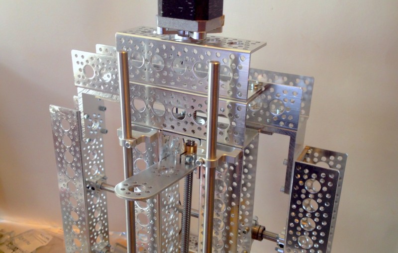
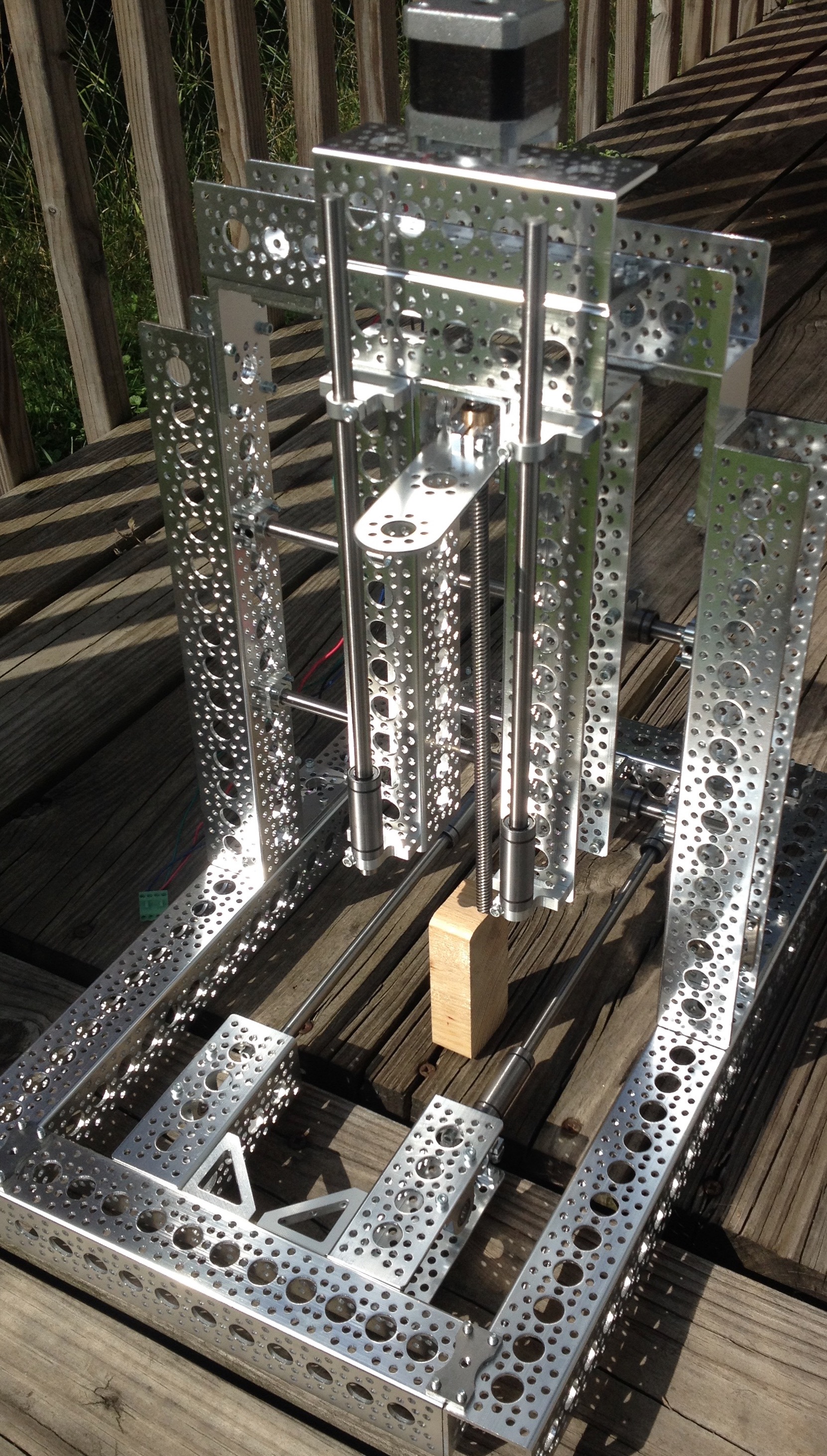
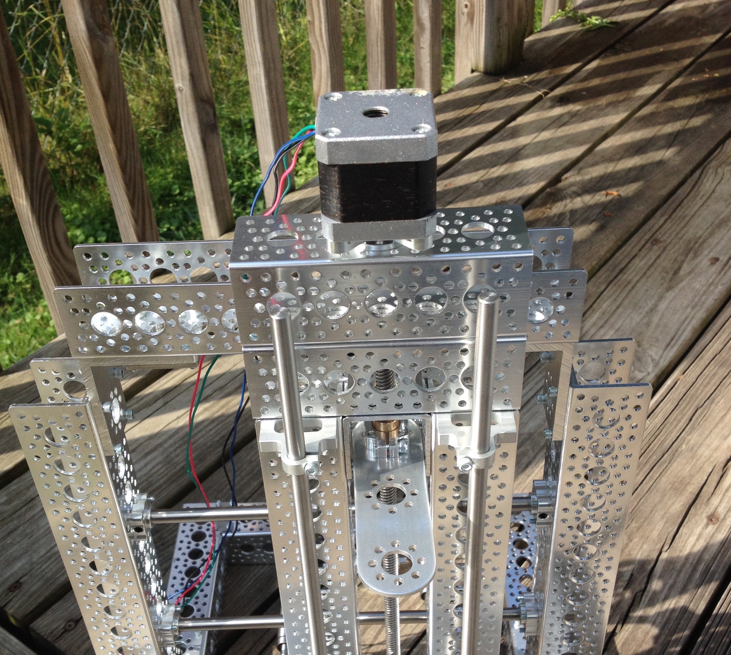
I’m choosing a fairly standard gantry setup where the Z is (currently) actuated by a NEMA-17 stepper that turns a lead screw. The product line includes two different nuts and they’re designed so well that gravity alone makes them turn — hold onto the nut and the lead screw spins out of it. Right now the 12″ lead screws in place make the gantry seem very tall to me. The top of the Z motor is around 17″ off the table. How much lift the toolhead will have when done is hard to guess when I don’t have a spoilboard in place and I don’t have a spindle.
One of the biggest problems I’ve encountered thus far with my “building set” approach is that I find myself limited by the strictures that make the set a set and not a random assortment of pieces. There has to be a system of some sort, and right now the system is challenging me.
Hack It Judiciously
 Building a project out of a building set forces you to build it according to the system of that set — either that, or at some point you have to make a conscious decision to abandon the system. If the beams are only so big, you can’t magically make them bigger. If a beam is 100mm long, you don’t get out the hacksaw and make it shorter.
::record scratch noise::
Hell yes you can. Here on Hackaday we follow the ethos that if I bought it, I may, can, and should hack the hell out of it if that’s what I want to do. That said, if it costs money, and I can’t afford to buy another, I definitely will make double sure I’m doing the right thing.
Actobotics, the product I’m using features metal channels that are peppered with two different hole patterns, allowing a wide variety of parts to connect. The scheme has enough iterations that you can theoretically make a light-duty CNC mill, is my thinking. The advantage of a building set over custom machined parts is that I can change my project around at will. If I don’t like 9″ beams in a project, I can remove them and add 6″ beams. A set makes iterations a dream. Depending on the set you can also be assured that add-ons like motor mounts and bearings will be compatible.
But sets also restrict you. When I built my tall-ass Z and decided it was too big, my anticipated changes were limited by what the product provided me. Should I hack down some parts to make it the perfect height? Maybe, but not yet.
I have to acknowledge, and reject, the psychological component to this — that the parts have an intrinsic value such that the purity of the set is somehow more important than the projects I do with it. The most logical decision is to use the chopping bandsaw at the hackerspace to cut down the lead screw to whatever size I want. Either that or go out and source my own damned part without relying on what is available for a set.
However, I’m not doing any of that yet for the best possible reason: I still don’t know to what height I should build my Z. Do you have some advice for my current build? Have you been in the same ‘hack it or preserve it?’ conundrum? Let us know in the comments below.


I would try to preserve it as much as possible so that when you publish plans for it, the others who try to replicate the build will be able to do so and hack theirs if need be. This way your second iteration of the Z can be hacked and not upset the standard.
all those null force elements in the gantry are going to be a problem milling anything hard. you need some diagonals in the gantry and where it attaches to the base to firm it up or you’ll see lots of lost steps and broken cutting bits.
+1
Although it being open-loop already makes hard material a no-go, but he already said he is not building it for that.
Still you would see much much more rigidity with some diagonals/angles supporting the Z, and for thing PCB traces that will be crucial. Don’t underestimate what the spindle vibrations and tool load can do. You might be able to get away with non-rigid supports (steal wire under tension), maybe.
Closed loop is not a requirement for hobby stuff. People are even milling titanium with their mini mills converted with steppers. But rigidity is definitely the problem here.
Some guide rods from the top of the Z axis to the base ends with greatly improve stability.
While this kit may let you build a mock up of what you want, i’m not sure it will ever be as stiff as you want it to be and still reasonably affordable. I looked at actobotics assortments and man thats expensive. I hope when you finish this project you’ll clue us in to how much it all cost you.
I did have this thought: if you need a “custom” part that will jive with the actobotics stuff, you could buy a cheap set of transfer punches and some aluminum bar stock and make your own gussets with the matching hole patterns to the actobotics parts. That might let you avoid modifying the kit, but might also introduce inaccuracy, depending on how you use it.
Yeah, that’s always been my lament about the Actobotics stuff is that it’s just too damned expensive. Great stuff, it’d be nice to have an unlimited budget to buy that stuff but I don’t have one. So I put my money into building a nice CNC machine so I can use it to make parts instead.
You may not need max *travel* to be cutter height + stock height + clearance. If you only plan to cut something 5mm thick, your cutter is 50mm long, and your desired clearance is 5mm, you can get away with only 10mm of travel. From zero (cutter touching spoilboard), moving up 5mm gets you out of the stock and another 5mm gets you your clearance. You can also set your spindle (or router or rotary tool) to overlap your z-height mechanism like on the X-Carve:
https://discuss-assets.s3.amazonaws.com/original/2X/b/b2aba59a08d1f0d54b0a80be9c4a7169448f3bee.jpeg
Finally, the end goal will shape the build. Be clear about what you want before you start. If all you want to do is pen plotting and PCBs, the requirements are a whole lot different than for cutting 1-inch aluminum!
With any of these machines I would suggest setting a design goal of being able to cut 6061 aluminum sheet. Even if it has to go really slow and make shallow cuts it is worth it to have a machine with this capability. I say this from experience – I built a giant CNC plywood cutter and it worked great, but then one day I needed to put holes in an aluminum sheet and when the bit hit the metal it creeped a little bit away from the intended drill location
So now I need to completely redesign and rebuild the machine. On the upside I get to upgrade a lot of the components and implement a better design from lessons learned on the first one.
since your rigidity requirements are low. I would suggest turning your z axis around. with the linear bearings fixed on the support structure somewhere and the lead screw and stepper on the moving z axis. that way your max part height is not limited by your support structure as it is now. kind of like this
http://cdn.instructables.com/F8S/G95S/HMVJDE8H/F8SG95SHMVJDE8H.LARGE.jpg
stability is a factor.
You can say that again. Embrace The Triangle.
Acrobotics if the government was paying but, as it’s me that’s paying, mine is being built from Ikea curtain rail and cutting boards.
starting from such a kit may be needlessly limiting, expensive, and setting up for failure.
given it is a robotics kit, keeping the weight down was the beginning criteria. so, aluminum, and lots of drilled holes. (both enemies to rigidity and stability)
it may do to start mixing and matching from your local hardware store for such things, but it may be interesting to pick and choose out of the robotics kit. (use steel channel for the outer frame and rails, and then the light robot parts for gantries and things that need to be lighter so they move well)
Aluminium is a rigid material – it have other problems but rigidity isn’t one.
The design of the set is a problem though, there are (as you mentioned) a lot of holes and it uses bent thin walled sheets rather than solid blocks. Still worth it for an experiment – the forces for milling PCBs aren’t great.
Square steel tubing is cheap and available in a wide range of dimensions and thicknesses. It’s also *very* straight, at least in the heavier gauges. Some 2″ square, 3/8″ wall stock my Dad bought is straight to 0.001″ in 3 ft which is the accuracy of the longest precision straight edge I have.
Even very light gauge steel square tubing will be much stiffer than aluminum U channels. One suggestion is to get some drill bushings to fit the holes in the channels and use that as a jig for accurately spotting holes in the steel tubing. You can then enlarge the holes and be assured of precise locations on multiple matching parts.
I strongly urge you to familiarize yourself with the appropriate deflection equations and calculate the deflections for various dimensions and loads. Machinery’s Handbook should provide all the information you need.
Agreed, machines are big to ensure they have a large cross-sectional area to improve rigidity.
Mill builders also know that sand/lead filled cast iron is more dimensionally stable, and ultimately can improve milling speeds.
For panel rough cutting, a carbon-steel box channel frame will certainly be better than something put together with fasteners in aluminum.
Even if the user is cutting foam or wax, the milled surfaces have a better chance to be flat and parallel.
Dan Gelbart gives a basic 1st year introduction to the machine shop:
*the difference between rigidity and stiffness in the series:
https://www.youtube.com/watch?v=MtxA20Q-Uss
*why bad surface finish makes poor mechanisms
https://www.youtube.com/watch?v=cwdoUjynpEk
Great Documentation and Good Advice from comment section.
To 1st timers (say a 4th grade Homework Assignment). The break down is this. When cutting/removing materials drill/mill/bore/saw the excess materials don’t magically “go away”. Everything from Hand saws, Metal files, Drill Bits; form chips/swarf that bind to the cutter. This is a “big deal” when working with automation because you want the proper “feeds n speeds” for the materials you are working with. Moving too slow may burn up or damage the medium (balsa, fiberglass boards, even polystyrene) you are cutting. Moving too fast and the cutting tool will lock up and damage itself, the tool platform or yourself and others.
Still it looks like it would be a fantastic skeleton for epoxy granite!
exactly this! +1