When last we ran into [Daren Schwenke] he was showing off his 6-color delta printer that changes colors seamless mid-print. Right now he’s working on a printer that uses tensioned cables to precisely move a toolhead while maintaining enough solidity that [Daren] can tap on the toolhead without it budging at all.
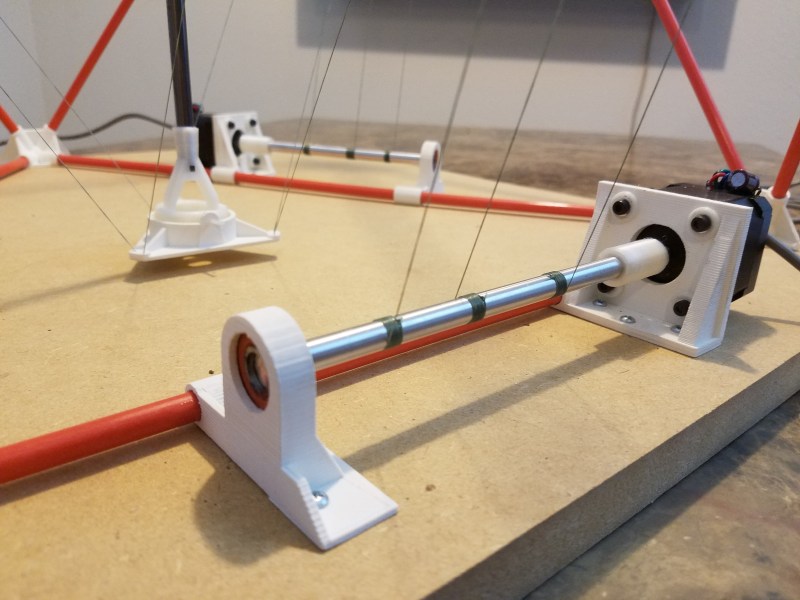
It’s much more simple a rig than a gantry-style 3D printer, with a chassis shaped like a geodesic polyhedron consisting of fiberglass trusses (those driveway markers) secured by 3D-printed lugs, all controlled by a Beaglebone Green and four steppers. A key element of the build is the central steel rod, a 4′ repurposed garden stake which serves to stabilize the whole toolhead. In terms of build diameter it can scale from around 200 mm to 600 mm. [Daren] aims to using Machinekit’s tripod kinematics for control and he also learned a bunch from RepRap’s Flying SkyDelta project.
For more 3D-printing goodness, be sure to check out [Daren]’s aforementioned 6-color delta.


Took me a while to realize that there is a rod pushing down on the tool holder which is why it doesn’t go all bouncy. Very clever.
yeah, when he snapped it I was like wtf? thought it was a bowden tube.
I was instantly jumping ahead trying to think ways to reduce that broom handle to something more manageable.
You can pull down with a pulley on the bottom instead, but it cuts into your build area then. Also, the longer the ‘broom handle’, the less you need for a spring to make up the geometric difference between winding and unwinding. 2X rod length seems a good compromise and fits well with flat packing.
It’s unreasonably long considering the size of the machine and its build volume.
The rod shown in all these pictures is from before it was cut down. It’s not that long anymore, but it is still ~2X the height and 3X the build height. This will never be the most space efficient printer, but I bet it will probably be one of the cheapest to make.
I mocked up some other cable/rod solutions which reduced the height of the rod needed, but that solution was by far the lowest mass affecting acceleration in the XY plane. Mass acceleration in the XY plane directly translates to limits on your printing speed.
It took me even longer to realize that, in each of the 3 steppers, the cable in the middle is winded in the opposite direction of the 2 outer cables to keep the tension.
And having that pulley design, the printing volume can be a cylinder instead of a cone while keeping the tension.
Very clever design :-|
thank you renato you explained the last piece of the puzzle for me to understand this thing :)
Wow. Thanks to the scalability and ability to “flatpack”, the scaled-up version might be used for things such as building-printing. Amazing design idea!
So how is the rod pushed down? is there a 4th motor pushing it down or is it by gravity?
I don’t really get it.
Anyway really nice design. What i like most is the Octahedron frame. Platonic solids are always the best choice when you have to chose a frame geometry. Always!
The “spool” is those metal rods. The center line goes to the top of the rod, the other two to the effector. Tightening the pair loosens the single one and vice-versa — keeping the down-force roughly constant. It’s very clever.
I wonder how is the homing is done.
Good catch! I believe that it isn’t, yet. In the end, you probably have to manually bring the head to a known place (or nearby) and call it home (or search locally for a marker).
The homing switches have yet to be fabricated, but the current plan is this.
Manually move the effector to roughly the middle some distance above the bed (to keep it from bottoming out).
Start homing. Each axis extends one at a time, which in turn retracts the push-rod cables.
The push rod cables have a stop, which triggers your homing switch.
Each axis then returns to the middle.
Machinekit has this homing sequence built in, so I don’t even need to write it.
Looks like a design that could be used to apply CNC to a pattern torch or profile cutter. https://www.youtube.com/watch?v=FikAaMMNCxo
They use a motor driven magnet in line with the torch or plasma cutter. It rolls around the edge of a steel pattern, which must be 1/2 the magnet diameter in all dimensions. Cutting sharp corners is difficult to impossible. The magnet can get stuck if an inside corner is too sharp or it may come off the pattern on a too pointy outside corner.
To apply CNC a frame could be built around the top with 3 or 4 motors with cables to a ring that slips over the magnet. Set the magnet motor speed to 0 or just leave it off.
The cutting area of one of these is of course not a quadrilateral. Could either limit it to the largest quad that fits with the arm’s reach or make it trainable to program in the full area.
Depending on where you are, a used one of these may be found pretty cheap, especially if being gotten rid of by a shop that’s upgraded to a CNC gantry for cutting.
Thank you for sharing!
Whaaa, that’s so clever that I couldn’t figure it out until I saw a full picture with it:
https://cdn.hackaday.io/images/1006601507425978008.jpg
And it can all be folded flat.
And it’s all sticks and strings and spring (try to say “sticks and strings and spring” 5 times in a row as fast as you can).
:o)
That’s an amazing design.
Hats off to you, Sir!
Thank you. It might actually turn out like it is, so of course I’m trying to ‘improve’ upon it already.
I have a bad habit of waiting until a project is nearly complete before trying to document it. Building stuff is more fun after all. This one I got started with documentation just after I assembled the parts for the first time, so now you’ll get to see some of the iteration and improvements at least.
I’ll still probably end up going back and having to explain a lot of the initial choices I made which I wouldn’t have to do if I had just documented it from the beginning. I’m getting better though.
Counting the stepper steps wouldn’t be overly repeatable, since there’s no moving guide to stop the thread overlapping. A joystick type arraignment om the pole wouldn’t be accurate enough to be made cheap enough. Maybe paint a stripe on the threads and use optical encoders.
The best option I could think of would be a combination of the rf usb sketch pad with traces under the work bed and send a frequency into the heating element in the head as the transmitter. Coupled with ir leds around it and receivers on the supports to triangulate the signal. Keeps the head light
Just let the spool rod move along its axis, maybe using a small thread at one end as a guide, so the wire spools/unspools always at the exact same spots. The stepper coupling would be funky, though.. you could use steppers with through mounting holes (with bushings? reamed?) so you could mount them to slide on four bars.
The ~500mm distance from the pulleys to the spooling rod make it so the thread never wraps on top of it self. The start position on the rod is lined up so they also spool up tightly wrapped. This large distance also minimizes positioning error with wrapping. Mathematically, the positioning error which will result when going from a full spool to an empty one was < 0.012mm so I just ignored it.
You always end up wrapping up as a single layer until you run out of flat space on the rod. As designed, that will happen when you use somewhere on the order of 1 meter rods for the corners. Of course you could just use a larger spool rod at that point and keep going, but you will sacrifice accuracy then.
The positioning error with wrapping was the first thing I thought of when looking at this. Thanks for clearing that up.
https://twitter.com/twitter/statuses/920362896952930305
I wanted a cheap 3D printer with only ropes and without expensive components. Your project shows me that it is possible.
But I’ll do some things differently.
The vertical bars form an equilateral triangle. I reduce the upper angle from 60 ° to 52 °. This saves space on the floor area.
Instead of the stepper motors I use the mechanics of 3 old, defective inkjet printers. That’s good recycling. I use the shaft to drive the paper, the encoder and the motor.