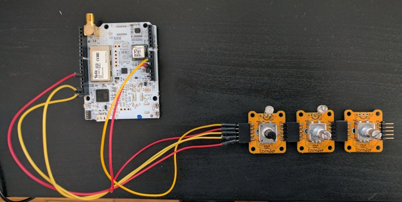
We’re digging these daisy-chainable encoders built by [fattore.saimon]. Each module consists of a rotary encoder attached to a PCB with a PIC16F15386 on the back. As we’ve covered in the past, the Microchip released their feature-rich PIC16 microprocessor just this year, and it’s great to see them start to crop up in projects. With 4 address jumpers on the back of each PCB, [fattore.saimon] is able to connect up to 16 of the encoders on the bus. The modules also have male and female plugs so he can connect them physically as well, to simplify wiring. Each module also has a PWMable bicolor LED for keeping track of each encoder’s setting.
If you’re interested in making your own you can buy the PCBs from Tindie or download the project files from the creator’s GitHub, including an Arduino library.
We love encoders here on Hackaday — building DIY encoders, as well as using them in projects like this precision cutting jig. And definitely read our colleague [Al]’s great piece on encoders.


Lol. Maybe he should consider reworking the I2C pull-ups.
Even if you scratch the Vcc connections, you’ll end up having all
16×2 resistors in parallel, between SDA and SCL.
Pullups can be disabled by removing drop of solder from a pad. But that causes different problem: after removing that drop from every but one board in 16 board chain, you get a resistance of 627 ohms between SDA and SCL. Not a good idea IMHO…
Yes, you are right about the pull-ups resistor.
But this problem is easily solvable by removing the resistors R9 and R10 from the PCB if you don’t need the pull-up.
I’m already working on a new HW release with this problem solved.
Thank you so much!
I’d accuse the article author of burying the lead, but he doesn’t even mention it. These are multiplexed to an I2C bus. Initial reaction as written is “so what” and “there’s other simpler ways to multiplex a few decoders, without involving a PIC on each….” … but these have more utility when you’re using I2C or it pre-exists in a system and you add to it.
One of possible solutions is to use I2C GPIO Expander such as PCA9555.Using a MCU for such task seems quite overkill
PIC is cheaper.
Speaking of price, I think, the cheapest solution would be without I2C on modules at all. IIRC encoders are pure mechanical devices, which allows us to connect their corresponding outputs together and just multiplex encoders’ inputs. If someone really want to use I2C bus he can use single microcontroller to control them all.
In mass production lots of MCUs in single device is a bit of pain.
I bought 30 PIC16F15323 for 0,57€ each, the PCA9555 cost 0,93€ in pack of 100pcs.
With a GPIO expander there is the possibility to miss some edges of the encoder output and the MCU have to be very reactive in order to manage it.
Smart encoders comes to mind, both in conditional triggering, and on-the fly reprogramming.
I love the modular idea but I am stuck on the 16 board limitation.
I can imagine lots of these in a modular audio synthesizer or mixer but 16 addresses just wont cut it.
If you could program and store an extra 4 bits of address in the micro-controller then you could easily have 256 (or more) addresses or boards and that would cover the addressing issue. Does this PIC have FLASH?
I wounder though if it is best to read them by addressing or reading them (or write to) in the order they are connected like the flexible multi-color LED strips or neo-pixels.
I can imagine this being expanded on so there are many different types of I/O and in that case addressable modules would make more sense as they would have different purposes (not just different functions) ie this is volume and this is balance both modules function the same but have different purposes. Something that also has a different function is – this is the volume and this is the equalizer display – completely different function.
In a “tortilla” kind of way – these different protocols are just different code – more PCB config jumpers and you could just choose and reconfigure.
From a coding point of view – for the coding of the Micro that is driving the bus and reading the I/O. Addressing is much easier especially when making changes to the layout or have different boards with different functions.
Perhaps have on special board or simply a reserved protocol sequence to be able to program in config details like address and chosen protocol.
Standard I2C supports either 7 or 10 bit addresses. So either 127 or 1023 devices can be supported on one bus (address 0x00 is reserved as a general call, IIRC)…
The firmware of the PIC microcotroller is available. You can configure the I2C address as you want, there is also the possibility to set the address in 10bit mode.
But you have to reprogram the PIC microcontroller.
I will just use 16 ADC pin to read(in case the processor has)
With price of 7USD per encoder that’s a very expensive solution to a very simple problem. This is just a bad design. With this micro one can read 4 encoders with buttons or 4 encoders without buttons and drive 4 LEDs. With additional 3 chips one could read 64 encoders with buttons. And with two more chips one gets 128 LEDs too…
There is also an error in the article: [fattore.saimon] uses PIC16F15323, not PIC16F15386.
In this project i’m using the CLC module for reading the encoder, the PIC16F15323 it has 4 CLC modules that you can read maximum 2 Encoder. If you want to read 4 encoders you have to use the GPIO and the interrupt-on-change that is a bit complicated, plus you have to make a custom board and firmware, and lose time on that.
The aim of this project is to make ease to use multiple encoders even without experience on electronic.
You don’t need CLC or interrupts on change for reading encoders. Just use a shift register or BCD to decimal decoder to select a encoder, and read its pins with micro. Or use more shift registers to read state of all inputs of all encoders or buttons. You included debounce circuit in the design, but even without it you can reliably read the state of encoders every few milliseconds by using a timer interrupt…
Go to http://www.ucapps.de > project archive and check out MIDIbox64(E) projects.
The way I would probably do this is to have some basic and cheap shift register chip on each board. There are a lot of shift register IO chips on the market now.
I would then have these read at high speed with a CPLD and have the CPLD convert the quadratures to registers on the other side for access by the micro-controller.
The micro could just read a register that says there has been +2 clicks since the last read or -1 clicks since the last read … so that the micro doesn’t have to poll very often and doesn’t have to respond to interrupts that demand low latency. You could sill use a much lower priority interrupt if needed.
I haven’t seen much by way of a serial IO shifter that is so small that it would suit this application unless you just used a bog standard 74xx series parallel in serial out but then you would also need a serial in parallel out for the LED.
Most of the serial IO I see can drive a complex LED display and have several buttons.
I couldn’t find “MIDIbox64(E)”
I like it. These encoders are nice, but on the hardware side they are boring repeating lots of connection devices. So a bus system is a very nice idea.
Suggestions:
— set the i2c adressvia i2c command (permanently stored in EEPROM)
— make the pcb much much smaller and front plate friendly
—- no side connectors, no holes etc.
—- connector on the backside
—- because the rotary knob is screwed into the front plate
— no pullups at all (the are a real pain, every modul on eBay has its own pullup today. So wrong.)
— move the smd parts to the othere side and allow connector pads on the now free side
The PIC16F15323 seems to have no eeprom, so I would use a attiny84/85.
Hey, chinese developers out there, do you hear me?!
The PIC can rewrite its flash memory (self write of program memory) so no need for eeprom