Low power devices are always intriguing, as they open up possibilities for applications with the need to operate remotely, or for very long periods without attention. There are all manner of techniques for powering such devices, too, such as using solar panels, super capacitors, or other fancy devices. The Micro Power Snitch is one such device, which can report wirelessly on your AC-powered appliances.
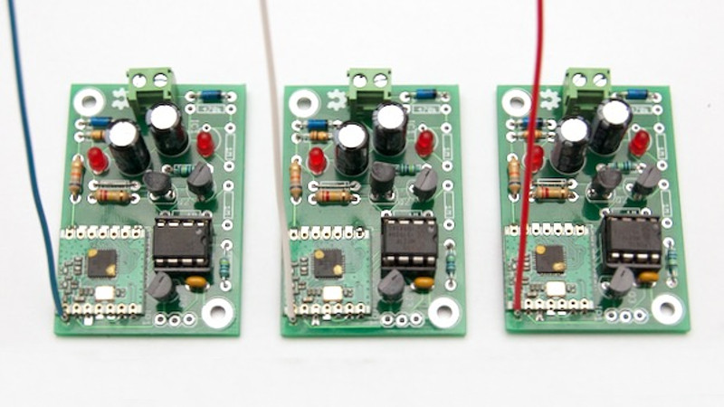
The device is built around a tiny ARM microcontroller and an RFM69 radio module. The entire circuit is run by leeching power from an AC current transformer, wrapped around one of the power lines of an AC appliance. When an appliance draws over the minimum threshold current (500W on 230VAC, 250W on 115VAC), the device sends a packet out, which can be received and logged at the other end.
The best part of this project, however, is the writeup. The project is split into an 8-part series, breaking down the minutiae of the concepts at work to make this possible. It’s a great primer if you’re interested in designing low-power devices.
We’ve seen some of [jcw]’s power research before – such as this guide to the effects of code on power consumption.
[Thanks to Ronald for the tip!]


Gotta read this!
Its not really “stolen” power.
Just a transformer unless you clip it onto wires outside your meter.
It’s a neat idea. I had started working on something exactly like this, but I haven’t had enough time to get back to it. I was going to report via WiFi, and it was going to take a fairly long time to charge a cap enough to send a single report. I intended to send one report an hour when harvesting from a 60 W load, but I definitely wasn’t there yet. I hope to make progress on that project again someday. If anyone’s interested it’s in my profile.
While your comment sounds quite facetious, I hope it was genuine thanks. The Capt had an idea and documented where he got to, which can only make it easier for the next person to build upon his work – that is how progress is made!
If you’re using an ESP8266 or ESP32 solution look into ESPNow, it uses way less power since it doesn’t use a wifi connection, just the bare radio. Andreas Spiess did a video on it just last week.
My idea is more intrusive: a pair of back-to-back diodes (maybe series arrays of diodes) in series with the load, and a voltage boost converter to pick up this tiny voltage over the diodes and turn it into something usable. This should work even with negligible current draw from the load, although it would waste some power as heat on the diodes. Obviously it would distort the voltage curve, offsetting down the positive half of the cycle and offsetting up the negative half-cycle, thus giving a lenghty zero-crossing point, which might be troublesome for inductive loads. Also the voltage output would be floating over mains voltage, thus it’s a safety risk for users interacting with it.
I did this in my teens at my bedroom light switch. This allowed a cap to charge that kept a triac triggered, keeping the light on. When switched off, the electrolytic cap would gradually discharge, providing a dimming effect until 50% duty cycle was reached, thereafter a sudden switch off. It was nessasary because my bedroom floor was so cluttered with half built, half taken apart stuff that getting to my bed in the dark was nearly impossible.
I just wear boots in bed
You want anti-parallel diodes, not back to back (series). The latter would prevent any current from flowing, until the diodes break down.
For inductive loads this “lengthy zero crossing” does not matter. Current will continue flowing until it commutates. Yes, it distorts the waveform a little.
In fact this solution is used in various “master-slave” power strips, which switch monitor and or printer with your PC. This is OK, for smallish loads of 100 to 200 watts. Otherwise the diodes waste much power.
“Stolen” only in the sense of harvested surreptitiously – just requires access to a single wire (live or neutral) to clamp around. Full galvanic isolation up to the spec of the current transformer. Most country domestic building codes have wised up to C.T. use and do not place onerous restrictions on who can install them (YMMV).
As with anything “mains” related, due care and attention is needed – an install that cuts no wires, simply clips on the monitored circuit and never needs a battery swap is a great help.
Where can I order one? I am mostly a lurker here but I thought you guys might know. I know PCBs can be ordered in various places although I don’t remember exactly where right now. But is there any site or service which can build the whole thing for you?
It is Jeelabs blog, there is a “shop” link at the top of the page.
Something is missing here (sorry no time to go through all the articles). It should be that the less load you have, the more you will wait for the capacitors to charge. So the minimum load should not be that high, unless it was made like that on purpose?
@electrobob,
Correct. A frequent stream of RF reporting packets clearly needs a substantial energy harvest – relax the frequency (and accept a minor ‘start-up’ lag) reduces the energy needed substantially and hence lowers the minimum useful detectable load current. If there is sufficient slack in the monitored cable, multiple turns through the C.T. jaws also reduces the detectable threshold.
Combining both methods, a 15-20W load is observable in practice.
Having a threshold can sometimes be useful e.g. to distinguish between a “sleep” mode and hungrily active.