
I always find it interesting that 3D printers — at least the kind most of us have — are mostly open-loop devices. You tell the head to move four millimeters in the X direction and you assume that the stepper motors will make it so. Because of the mechanics, you can calculate that four millimeters is so many steps and direct the motor to take them. If something prevents that amount of travel you get a failed print. But there is one part of the printer that is part of a closed loop. It is very tiny, very important, but you don’t hear a whole lot about it. The thermistor.
 The hot end and the heated bed will both have a temperature sensor that the firmware uses to keep temperatures at least in the ballpark. Depending on the controller it might just do on-and-off “bang-bang” control or it might do something as sophisticated as PID control. But either way, you set the desired temperature and the controller uses feedback from the thermistor to try to keep it there.
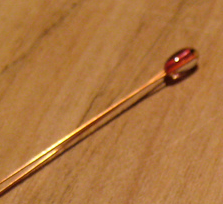
If you print with high-temperature materials you might have a thermocouple in your hot end, but most machines use a thermistor. These are usually good to about 300 °C. What got me thinking about this was the installation of an E3D V6 clone hot end into my oldest printer which had a five-year-old hot end in it. I had accumulated a variety of clone parts and had no idea what kind of thermistor was in the heat block I was using.
Does it Matter?
When you build the firmware for your printer, you get to tell it what thermistor you are using. There are a few printers that can switch the thermistor type at runtime and — of course — you could just adjust your temperature settings to account for any error if you knew what they were. You usually use a negative temperature coefficient (NTC) device where the resistance goes down as the temperature goes up. But exactly what resistance corresponds to what temperature depends on the device.
So for my upgrade, the old hot end had a thermistor in it that — I think — was made by Honeywell that the firmware knew about. The new hot end was a total unknown. Most (but not all) common thermistors you’ll use in a printer read 100 kΩ at room temperature and that was true of both of these, as well. I wanted to understand how much off my temperatures would be if I picked up the wrong conversion. Surprisingly, while there was plenty of information about how to read a thermistor, I had not seen much data about error from using an incorrect temperature curve, so I decided to take matters into my own hands.
But First
First, it might be worth to think about what really happens in a typical 3D printer’s temperature sensor. Sure, the thermistor changes value, but what then? Most controllers will have a resistor divider with a fixed resistor and the thermistor and then use an A/D to read the voltage.
You don’t want to pass too much current through the thermistor because that current causes some heating and is a source of error. A typical printer will use a 4.7 kΩ resistor at 5 V to excite the thermistor and read the resulting voltage. Suppose the thermistor is at 500 Ω. The voltage across the thermistor will be 5 * (500/(4700+500)) or about a half volt.
I mentioned that most thermistors you’ll find in a printer read 100 kΩ at room temperature. You might think 500 Ω seems kind of low. In fact, as the device gets hot, the resistance rapidly falls off. A 500 Ω resistance corresponds to around 190 °C in a typical 100 kΩ thermistor.
The microcontroller running the printer has to do the opposite math. That is, it will take the equation above and solve for the resistance. In other words: 0.5 = 5 * (R/4700+500) so solve for R. The problem is you don’t want to set your filament temperature in ohms! You want to use degrees.
The best way to compute temperature from a thermistor reading is the Steinhart-Hart model. This requires three parameters and a little number crunching. However, most 3D printer software uses a simplification that uses just the second parameter, or beta, of the thermistor.
Rather than give you the formula, I’ll point you to this spreadsheet. Column A has some resistance values and the other columns have different beta values and show temperatures in degrees C. If you really want to dig into the math and other applications, check out [Peter Vree’s] video, below.
Big Difference?
Armed with that spreadsheet, it is pretty easy to figure out how big a deal it is to be out of tune with your thermistor. Of course, you’d like to have the right value, but in the case of a generic thermistor, how big of a deal is it?
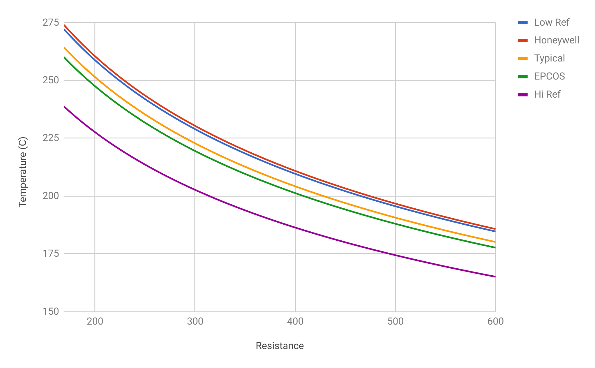
My methodology was simple. I went to Digikey and searched for thermistors. I used their filters to only look at 100 kΩ NTC devices that could read at least 300 °C and specified a beta at 100 °C. The beta values ranged from 3988 to 4280 and based on price and quantities, the real range was even less spread than that. For example, Digikey only had about 180 of the device with a beta of 4280. Not very scientific, I’ll admit, but it did give me a range of beta values you might expect to find “in the wild.”
If you note on the spreadsheet (and the graph below), there’s not a lot of temperature difference at the typical range you’ll print plastics like PLA, ABS, and PETG. Of course, you could get unlucky. If you do have that bottom-most curve, the temperature is a good bit off for that one. Or maybe you have a one of a kind thermistor that has some wacky value that will be way off. But statistically, you’d think you are going to be in the ballpark even if you can’t change the thermistor table. Now, if either thermistor has a different room-temperature resistance, all bets are off. But most of the 3D printers I’ve seen do use 100 kΩ sensors.
The Result
Although it shouldn’t make much difference, I did make an educated guess based on some heuristics and changed the thermistor type. I thought about trying to set a precise temperature on the thermistor to get a few more data points but decided it wasn’t worth breaking out the sous vide cooker.
After all, every printer is a little different and the temperature the plastic sees probably isn’t the thermistor temperature anyway, so there’s always a little “dialing in” required to determine what temperature your printer needs for a particular job. A difference of five or even ten degrees, then, will be in the noise. You’ll find out your PLA is too runny at 210 °C and drop the temperature to 190 °C. Or perhaps ABS is causing extruder skips and you’ll goose the temperature up a few degrees. You are going to have to do across different brands, or colors, of filament anyway.
 At the end, though, I got great results. Who knew that what might be the tiniest part of a 3D printer could be so important? If you look carefully in the photo to the right, there are two thin Teflon-coated wires coming out of the heat block. That’s the thermistor, whatever brand and model number it is.
Thermistors, of course, have lots of other uses. They can be used to limit inrush current, provide temperature-stable bias, and — of course — sense temperature in many different situations. For example, they can be the heart of a very minimalist soldering iron controller.


Damn, your illustrator is good!
he sure is, if you have seen one of the omnibus’s even more great art, I will hold on to my two copies until I die.
Yep, there are some really nice pieces of artwork on some of the articles here. It really spices up the articles.
Joe Kim’s Amazing. If you want to scroll back through his work check out the original art category:
https://hackaday.com/category/original-art/
“tell the head to move four millimeters in the X direction and you assume that the stepper motors will make it so.”
And why should it not :
– perhaps of a mechanical issue… well if there really is such a problem it should stop anyway
– perhaps of some ugly drops of plastic (from the previous layer) are blocking the path of the printhead… hmmm, very likely (hate when that happens), but what should it do, rush into the obstruction with full force hoping the obstruction breaks or perhaps slowly melting the obstruction away? Or perhaps rush into the obstruction, causing the print to break from the bed or break a few layers.
Anyway… if the print fails because you missed some steps, you’ll have a problem that needs fixing anyway.
In those cases where the printer frequently misses steps for every bit of dust on it’s path, well then just simply increase the current which may require stronger motors or better drivers. Some drivers are really shitty, sold as rated for 2A, but are completely SMD and have no proper thermal connections but they do require a heat sink to operate (why, I ask you). It makes you think that the specified current is peak only, but some sellers fail to mention that and many cheap printers use these kind of drivers.
Anyway, closed loop positioning is the only proper way and really not so difficult with modern components. I wonder if it is a cost issue or is it a heritage from the past or are 3D printer manufacturers not willing to invest (development time) in this technology. Or (and that is what I expect) is the number of 3D printer in a production batch not large enough to justify the investment in a slightly more complicated design? Stepper motors are a dime a dozen (figure of speech) while DC motors with optical feedback are simply less common and therefore more expensive.
Depending on the (unknown) root cause of the failure to move, closed loop (servo) positioning may not offer much help over a stepper-based system, and could make things worse, by trying harder in an impossible situation.
Failure scenarios include:
1. Collision with foreign object, or model under construction.
2. Internal binding of structure due to warping or loosening over time.
3. Failure of electrical cable or sensor.
4. Failure or loosening of structural component such as a belt.
A servo will typically attempt to increase torque in response to an increasing position error signal.
Depending on the cause and strength of the obstruction, trying to blindly “power through” the obstruction could make things worse.
In some cases a simple optical tachometer (or low-res encoder) on a stepper based system can offer an ideal cost/benefit balance:
1. Tachometers add very little cost.
2. Tachometers could detect significant stalling events (and trigger E-stops), which would address many of the potentially most dangerous failure scenarios.
A lot of industrial servo drives have an error-out signal, usually to stop the machine when the required torque to reach the position is over the preset limits. That’s one of the nice things about feedback, you can actually detect the problem.
The new Trinamic drivers can detect stalls through spikes in the back EMF. As much as I want closed loop it’s not as big of an improvement as it used to be. The Prusa Original i3 Mk3 demonstrates this feature pretty well.
There are two main reasons why most 3D-printers doesn’t use closed loop system (even though it would be much better):
1. Using an open-loop system is usually “good enough”. Sure, you might run into problem a little now and then, but if your machine is built at least semi-properly, it won’t case an issue that often.
2. Most 3D-printers are built using an Atmega2560 because of the giant legacy that is Marlin. That microcontroller is most likely not able to handle the feedback from tachometers and run a 3D-printer at the same time (you’ll need some hardware support for it).
Don’t get me wrong, I think movement feedback would be really nice thing to have, but in most cases, it’s just not worth the effort (you would have to develop a new 3D-printer driver firmware to get it and move away from the crappines that is 8-bit Atmegas).
And that´s how I fooled my davinci into using filament other than xyz´s.
I did a bit of reverse engineering to find the Beta of the Nissan Leaf battery pack thermistors.
I took the three temperature probes and an I2C temp sensor, slowly swept the temperature, and then used the data to plot everything in Excel, used the average to find the Beta.
Then using the Beta made a table (4096 entries) where the ADC value is the index and the value returned is the temp in C.
https://youtu.be/GN4gHWU5lVU
A big part of my job is temperature control in the range of 10C to 100C (biomedical), with less than 0.1C error. While figuring out how to measure this accurately, I found a number of things that simply don’t work, and a few that almost always work.
The sensors I use (today) are 10kOhm @ 25C thermistors in a classic bridge formed from 10kOhm 0.1% tolerance resistors. a 22-bit delta-sigma differential converter reads the voltage across the bridge, while the bridge supply voltage (3.0V) is also the converter reference voltage. Power dissipation in the thermistor was kept to less than 100uW.
There are two problems with the hardware that can’t be avoided:
1) Thermistors from the same lot behave differently in the same circuit. Replacing one thermistor with another from the same lot (with no other changes to the system) produces a temperature difference up to about 2 degrees.
2) The bridge resistors have to be 0.1% tolerance or less to maintain measurement consistency between otherwise identical instances of this circuit.
These combine to require a calibration for every instance, although general “uncalibrated” (build it and test) performance produces temperatures within about 5 degrees. Quite good in most applications, but I needed better. Usually, a simple offset suffices, as the measurement slopes are almost identical near a setpoint temperature.
I tried to use the Steinhart-Hart model, but could never get the the errors down to where I needed them to be. I went in a different direction for the measurement and data conversion. I use the raw converter data at several known temperatures (5) to compute the constants of a 6th order polynomial in Excel (plot a graph, raw data is X, known temperatures on Y. Add a 6th order polynomial trendline (showing the equation, scientific notation, 5 places)). Implement the trendline equation (Temp = C5X^5 + C4X^4 + … + C1*X + C0, X is raw data) in firmware. Plug the raw sensor data into the firmware equation (as X), and it spits out the temperature (as Y) with high resolution for the general circuit. A single point calibration of the actual circuit requires only a small offset to the temperature (or C0).
This gets around the depending on the Steinhart-Hart model (and just provides an initial thermistor resistance with significant error) – you still have to model the bridge performance.
The nice thing about this process is that you can replace the thermistor with an RTD. The only thing that changes is the trendline equation constants. That’s next….
That’s science. Thanks!
I have been toying with replacing my thermistors with Pt1000 RTDs and a constant current driver circuit to get more precise nozzle temp measurements. With the tolerance and linearity of thermistors/thermocouples being…not that great, I’m kind of surprised it’s not standard already.
thermocouples are the way to go here. much more precise.
Not really more precise, just usable in more places, as long as the errors are acceptable.
When you look at the specifications for a K-type thermocouple, it usually reads something like +/-1.0% of full scale +/- 25degC. If the full scale temperature is 500C, and you’re measuring 250C, the error will be something like +/-5C+/- 25C, or anything in the range of +30C to -30C. You will get a reading anywhere in the range of 220C to 280C.
Then add to that the error of measuring your cold junction temperature (can’t dodge that bullet) because thermocouples actually measure the sum of temperature gradients along the length of their wires, rather than the difference in hot and cold junction temperatures, or an absolute temperature at one end.
Also, thermocouples shift as they age, as they experience heat/cool cycles, as their wires get flexed, etc.
Thermocouples *are* extremely cheap, well understood, and useful at temperatures where thermistors can’t go. They have their place. An extruder hot end is a good place, as long as you’re willing to adjust the temperature setpoint.
Thermocouples, using the standard interface boards, are actually less precise. Not to mention that I CANNOT use standard wiring to extend them and get a good result. A PT1000, or as E3D (and Duet boards) supports, PT100 sensor, can use any reasonable style of wire, with a 4 wire sensor having no error due to the resistance of the leads, and the 2 wire sensor only starting to have actual error margins above the noise floor if you use really shite wire or really long runs.
What thermocouples are is cheap, and easy to do basic stuff with pre-packaged kits. They are even harder to use when you need to extend them, and are annoying to deal with exotic issues.
I work on photocopiers (the BIG ones) and they switched to iR non contact thermistors years ago. Less wear and tear on the fusing rollers ;)
I bet! Are these devices anywhere near affordable for hackers? I can think of a ton of uses in the twelve seconds it’s taken me to type this response.
I did this for my car:
http://forums.tdiclub.com/showpost.php?p=5071140&postcount=43
http://forums.tdiclub.com/showpost.php?p=5081351&postcount=64
This is another reason why when someone else says they print the same material on a similar printer ten degrees hotter, you should be careful with comparisons. I look at each printer as being relatively correct but absolutely wrong. I’m sure the fact that I live at 6000ft and my printer is in the basement and I have a very stable power supply all add up to being different than yours. There’s not (much) benefit to knowing if 210C is really 200C. The only place I really care is if I’m trying to compare my temps to plastic recommendations or the specs of other parts (like PTFE liners).
“When you build the firmware for your printer, you get to tell it what thermistor you are using.”
Wow, I guess I never really appreciated how spoiled I am with a duet… I got the ormerod 2 largely because it came with good electronics, but I never really gave much thought to how the other half lives… building thermistor values into your firmware… not just updating the config file on the sd card, or sending the G-code to update the thermistor value on the fly…
I actually calibrated my thermistors by updating the g-code values until I got the system to report the actual temperature of the bed/hot end… then a quick double check on the reported bed temp vs the IR gun to validate that it all looked good…
Sure I could have just used the multimeter to check the resistance at room temperature… but this way didn’t require unplugging anything.
Agreed. Duet is the best controller I’ve used so far, for this and other reasons. The g code only configuration approach gets old but the platform is so expansive and flexible that it makes up for that. If a tinkerer wants to do anything even slightly unusual and can swing a Duet, they’ll probably love it.
“I actually calibrated my thermistors by updating the g-code values until I got the system to report the actual temperature of the bed/hot end…”
That right there is pretty funny… I spent many years as an Instrumentation Tech and a PLC programmer. Never failed that when a system had a problem, the operator always said “the actual temperature is X but the display is reading Y… I always asked what do you consider “actual” temperature to be and what is the accuracy of the device you obtained the reading with?