Face it, we’ve all at some time or other looked at our hot glue guns, and thought “I wonder if I could use that for 3D printing!”. [Proper Printing] didn’t just think it, he’s made a working hot glue 3D printer. As you’d expect, it’s the extruder which forms the hack here.
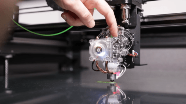
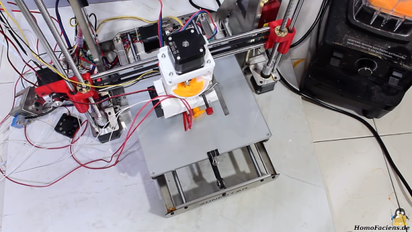
A Dremel hot glue gun supplies the hot end, whose mains heater cartridge is replaced with a low voltage one with he help of a piece of brass tube. He already has his own design for an extruder for larger diameters, so he mates this with the hot end. Finally the nozzle is tapped with a thread to fit an airbrush nozzle for printing, and he’s ready tp print. With a much lower temperature and an unheated bed it extrudes, but it takes multiple attempts and several redesigns of the mechanical parts of the extruder before he finally ended up with the plastic shell of the glue gun as part of the assembly.
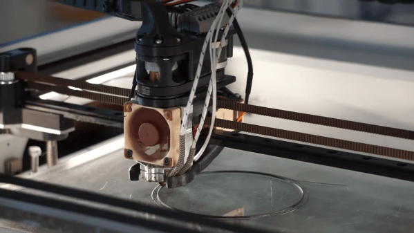
The last touch is a glue stick magazine that drops new sticks into a funnel on top of the extruder, and it’s printing a Benchy. At this point you might be asking why go to all this effort, but when you consider that there are other interesting materials which are only available in stick form it’s clear that this goes beyond the glue. If you’re up for more hot glue gun oddities meanwhile, in the past we’ve shown you the opposite process to this one.