Sometimes when you walk into a hackerspace you will see somebody’s project on the table that stands so far above the norm of a run-of-the-mill open night on a damp winter’s evening, that you have to know more. If you are a Hackaday scribe you have to know more, and you ask the person behind it if they have something online about it to share with the readership.
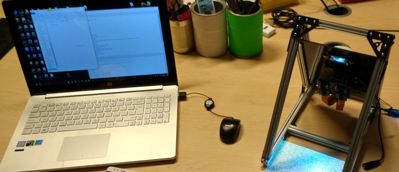
 [Jolar] was working on his 3D scanner project on just such an evening in Oxford Hackspace. It’s a neatly self-contained unit in the form of a triangular frame made of aluminium extrusions, into which are placed a stack of Raspberry Pi Zeros with attached cameras, and a very small projector which needed an extra lens from a pair of reading glasses to help it project so closely.
The cameras are arranged to have differing views of the object to be scanned, and the projector casts an array of randomly created dots onto it to aid triangulation from the images. A press of a button, and the four images are taken and, uploaded to a cloud drive in this case, and then picked up by his laptop for processing.
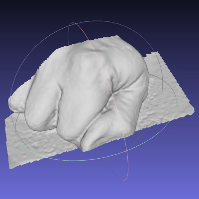
A Multi-view Stereo (MVS) algorithm does the processing work, and creates a 3D model. Doing the processing is VisualSFM, and the resulting files can then be viewed in MeshLab or imported into a CAD package. Seeing it in action the whole process is quick and seamless, and could easily be something you’d see on a commercial product. There is more to come from this project, so it is definitely one to watch.
Four Pi boards may seem a lot, but it is nothing to this scanner with 39 of them.


Very nice!
Any particular reason you couldn’t use one Pi 3 with 4 webcams connected to it? Seems like this is unnecessarily complex.
the pi camera is special. If you research it you will realize that 4 pi zeros with pi cameras is a significantly better project than 1 pi 3 with 4 webcams.
This product is also like your idea, you can also use ivport.
http://www.ivmech.com/magaza/en/development-modules-c-4/ivport-v2-raspberry-pi-camera-module-v2-multiplexer-p-107
I think it would give better results with 4 usb cams, rpi cameras are not cheap
and they have a really bad optic that you can’t adjust, not very good at closeup
You can actually adjust the focus of RPi cameras, either using pliers carefully, or better by 3D printing a small tool (designs are available on Thingiverse). This way it can be focused on really closed objects too.
As a concept this is a working model of a 3D camera for moving objects.
The Pi3 does not have enough memory to snap 4 pics before the object has moved on and distorted the image.
Imagination Dan, Imagination
Why do you think the object would be moving? There’s no indication this device is for scanning moving objects. In fact, it seems like the multiple cameras are specifically for scanning without the object moving, as otherwise you could just have one camera and rotate the object like more “traditional” scanners.
as far as i know, from using it in the past, few years back, VisualSFM only outputs a point-cloud, not a mesh with faces like in the meshlab screenshot in the article. Surface reconstruction (in meshlab) can be quite a challenge for some objects. Meshlab has gotten quite a bit better at not crashing in recent years, but for large point clouds it’s still a serious challenge.
i mean, it usually requires quite a bit of manual cleaning up, so fully automated, i don’t think so.
From the VisualSFM website:
“The SfM output of VisualSFM works with several additional tools, including CMP-MVS by Michal Jancosek, MVE by Michael Goesele’s research group, SURE by Mathias Rothermel and Konrad Wenzel, and MeshRecon by Zhuoliang Kang.”
Is the source code for VisualSFM available ?
Answer is no, but “SiftGPU (feature detection & matching) and PBA (multicore bundle adjustment), which can be easily integrated into any other SfM system” are.
You could have some neat effects with different wave lengths of light and pulsing the lights at different angles to see if you can change the detail. I seem to remember and article about that kind of stuff. Long time ago.
Think a Kinect might have helped?
I don’t get it. where did you find the info about what software he used. I’m unable to find that info on the linked hackaday.io page…
Given the intro they talked to him at the Oxford Hackspace in person.
I’m busy trying to persuade him to share more. And yes to the other commenter, face-to-face. THis was such a good project I thought you would all want to see it.
What camera model does he uses??
What’s the trick to get 4 pi zeros?
Exactly, it’s 2018 and the few shops that carry Pi Zeros or Pi Zero Ws are still out of stock or only send you one per order and warn you not to make multiple orders. And the shipping costs are 3x or 4x the actual board (at least in EU). Pi Zero Ws seems slightly easier to source though, perhaps because there’s more margin for the shop and less need to come up with silly kits to inflate the price. The short camera ribbon cable can’t be ordered at all other than with a kit.
Having friends.
Going to MicroCenter?
Faster i/o writes with a new usb3 board – chaeper than a pi3
https://www.aliexpress.com/item/Orange-Pi-Lite2-H6-1GB-USB3-0-Bluetooth4-1-Quad-core-64bit-development-board-Support-android7/32849206150.html
Solid and Hard works give you better instructive diagrams yet it has its own specific working challenges. It is touch stirred up for boss which can reduce executive speed for the undertaking. It require some less demanding updates.