One of my first jobs as a freshly minted graduate engineer involved the maintenance of a set of analogue chart recorders. They were museum pieces by the early 1990s: a motorized roll of graph paper across which a pen would traverse in proportion to the voltage on the input terminals. Inside was a simple servo, with a differential amplifier comparing the feedback via a potentiometer from the mechanism with the amplified input.
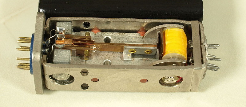
The recorders dated from the early 1960s, and internally their electronics were from the germanium transistor era: many Mullard OC-series devices, black-painted glass tubes with a red dot, and, unexpectedly, a large electromagnet connected to the 50 Hz AC supply with a reed switch through its middle, something completely new to an overconfident youngster who thought she knew everything.
What I’d stumbled upon was a chopper amplifier, a slightly ungainly and long superseded solution to the problem of DC amplification from the days before ubiquitous integrated circuit op-amps. We have become so used to DC amplifiers that just work, that we have forgotten that there was a time when such devices were an impossibility. The close matching of properties between devices on the same wafer allowed integrated circuit op-amps to achieve stable DC amplification in a way that the best attempts at the same circuits with discrete transistors had failed, but before they happened some desperate measures were called for.
The chopper amplifier relied on the simple premise that, using 1950s technology, it was difficult to make a good DC amplifier but easy to make a good AC amplifier. Thus a DC input signal was modulated onto an AC source, fed through an AC amplifier, then demodulated and passed through a low-pass filter to recover the amplified DC signal. In my chart recorders the modulating and demodulating was performed by the 50 Hz reed switch, and the germanium transistor AC amplifier was able to do a good job of working with the resulting 50 Hz square wave.
Chopper amplifiers were commonly found in instrumentation and other applications through the period until the advent of affordable integrated circuit op-amps through the 1960s. When these components arrived, they provided a single component that was a differential amplifier rather than the chopper’s single-ended amplifier, with better gain and a hugely higher bandwidth at a fraction of the price and with none of the complexity. You might imagine that the chopper would be consigned to history then by this development, but that’s not so! An integrated circuit op-amp is an astonishingly versatile component which can be had in many different variants to suite a huge array of applications, but it has one Achilies’ heel. It is difficult to make an op-amp with a low noise level at fractions of a Hz, i.e. at near-DC frequencies.
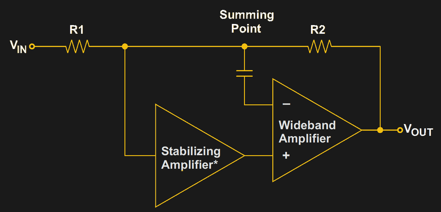
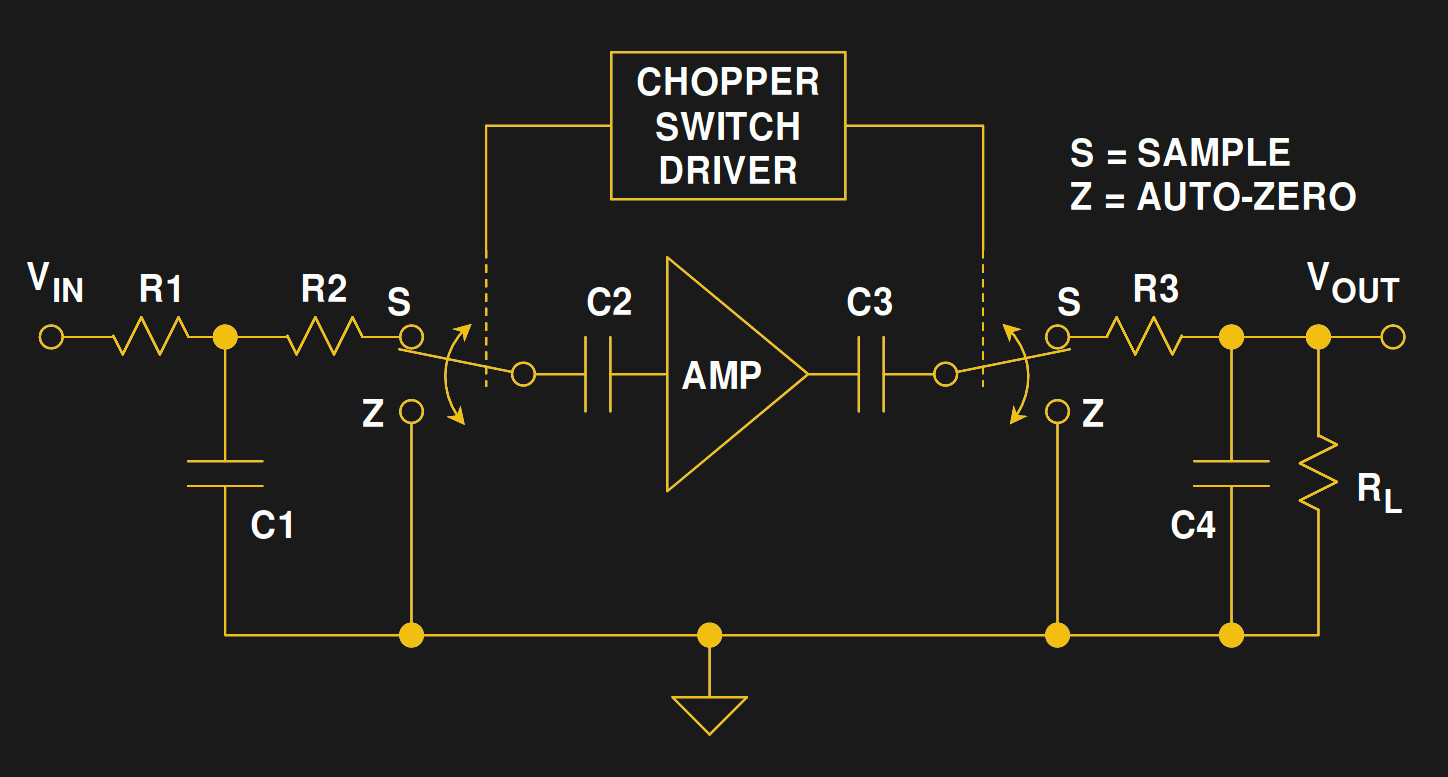
The solution to the problem of poor op-amp DC noise performance came from a return to the chopper, but only as an adjunct to the op-amp rather than its replacement. The chopper-stabilised op-amp is a standard op-amp configured as an AC amplifier with a traditional chopper amplifier (labelled “Stabilizing amplifier” in our diagram) in the path to its non-inverting input. This becomes a two-path device, with the high-frequency components being amplified by the op-amp with its superior bandwidth, but the DC component being amplified by the chopper amplifier for which the op-amp becomes simply a buffer. The whole circuit is still a single-ended one, but it has become a high-bandwidth amplifier with an ultra-low-noise DC performance.
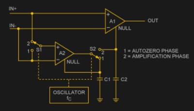
There is a final refinement of the chopper amplifier, and it is one which can be bought off the shelf from multiple manufacturers. The auto-zero amplifier uses a chopper amplifier and an op-amp just as the chopper-stabilised amplifier does, except the chopper does not contribute directly to the output. Instead it forms a pair of sample-and-hold amplifiers, alternately trimming its own offset as a differential amplifier and then trimming the offset of the other op-amp which does the amplification. This has the effect of reducing the op-amp’s DC noise by the same extent as the simple chopper amplifier, but while preserving the differential inputs of the op-amp.
It is unlikely that any of you reading this piece will deal with vintage chart recorders for a living, though the Hackaday readership never cease to surprise us. So if you encounter a chopper amplifier it’s likely to be of the final variety, an auto-zero amplifier chip that will probably appear to you to be as just another op-amp that you’re using for a strain gauge or similar. But even if the joys of maintaining a 1950s vibrating reed switch will never bring a wrinkle to your brow, it’s still worth knowing something about how they work. For further information I’d suggest your next port of call should be the multiple application notes and data sheets on the subject that can be found on the web or the few linked from this page. You can never have too many pieces of circuitry stored in your brain!
Image: a mechanical vibrating switch used in a vintage chopper amplifier. Binarysequence [CC BY-SA 4.0].


Actually, every one of us has a chopper-stabilized opamp right on our bench, that we use every day. DMMs use them to automatically guarantee a zero reading with 0 volts input. DMM chips as far back as the Intersil 7106 from the early 1980’s have had them.
A lot of modern multimeters do not use auto zero ADCs. Quite a few use Delta Sigma, a very versatile sort of device that really needs an article of its own. There are also low offset opamps that do not use chopper techniques, for applications like audio where the chance of adding noise is unacceptable.
https://hackaday.com/2016/07/07/tearing-into-delta-sigma-adcs-part-1/
https://hackaday.com/2016/08/11/tearing-into-delta-sigma-adcs-part-2/
:)
Before integrated CMOS integrating converters became available, many digital multimeters operated without automatic zeroing at all. The common method was to bias an input JFET stage to its zero temperature coefficient point and this works surprisingly well yielding good performance through at least 4-1/2 digits of resolution. I have a couple designed this way which I use for sanity checking because they do not suffer from charge injection like an automatic zero or chopper stabilized input stage can.
Delta-sigma converters by their nature chop their input stage gaining all of the benefits of such.
Chopper stabilized amplifiers are only used for digital multimeter inputs by novice designers because their high input current noise from charge injection conflicts with high input impedance. They are really only intended to be used in low impedance circuits.
The Intersil 7106 and similar integrating converters have automatic-zero rather than chopper stabilization as shown in the example above or as would be found in a chopper amplifier which always operates as an inverter. Instead of nulling the offset voltage between the inverting and non-inverting input, they null the offset when the common mode voltage is zero. This has the side effect of *not* removing common mode errors and the integrated CMOS voltage follower used for buffering limits linearity. This is not a problem for the 7106 because it is only 3-1/2 digits but integrating converters contemporary to it which provided higher resolution also had provisions for using a better external buffer.
My first internship in 1987 was with a company actively producing recorders. They did recognize that this technology was on the way out and they were switching to building printers.
In the ’70s, I had a surplus X-Y recorder that used vacuum tube (valve) chopper stabilized amplifiers.
Please do a blog entry on lock-in amplifiers.
They are still in use for ultra low offset amplifiers like low side current sense amps.
Those old chart recorders aren’t dead yet. I still use them every day at my job! They are quite temperamental and prone to stripping the teeth off their drive gears.
Chopping is still a subject of active research, and the vocabulary has evolved a bit. The circuit in the Analog app note (labeled ‘classic chopper amplifier’ above) now falls in the category of ‘offset cancellation’.
These days chopping is considered a modulation technique similar to radio: you combine the low-frequency signal of interest with a high-frequency carrier, run it through an AC-coupled amplifier with high gain, feed the output of that into a voltage divider that drops the gain back to 1, then remove the carrier. The AC coupling blocks the amp’s DC input offset voltage, and the amplify-then-divide step reduces the amplifier’s drift to 1/gain in the output.
The defining feature is that chopping produces continuous output. No matter when you look at the chopper’s output, it’s a low-offset, low-drift copy of the input.
Offset cancellation is considered different because it uses sampling instead of modulation: the circuit spends 50% of its time capturing its own offset-and-drift error, and 50% of its time subtracting the captured error from the amplified input. The output is a square wave that’s only related to the input half the time.
The big advantage of offset cancellation is that the amplifier can run at full speed during the half where the output is connected to the input. Chopping, like all modulation processes, runs into problems when the input is more than half the modulation frequency.
There are three main ways to deal with the square-wave output:
1) You can filter it, but that loses the advantage of being able to run the amp at full speed.
2) You can use a track-and-hold circuit to capture the parts of the output related to the signal, and skip over the parts that drop to 0V. That’s better, but the output is still only related to the input half the time.
3) You can use two offset-cancelled amps running out of phase with each other. When one is capturing its own error, the other is producing valid output. That’s called a ‘ping-pong amplifier’, and provides the best mix of offset cancellation and full-speed operation. It’s also the most complex though.. you need two complete amplifiers and a switching network for the outputs.
I think SDR detectors do this. A brilliant bit of work in the early 1990’s showed how to replace a mixer with a (quadrature) chopper. It eliminates the need to do a product of high freq signals. Turning the signal off and on is the same as multiplying by a square wave. And since a square wave is the sum of all the odd frequencies in a Fourier Series, well you can see where this is going. And there is no distortion as in semiconductor mixers that use the non-linear regions to get products.
I still have an old Grass-Telefactor setup we used for EEG but was originally I think used for polygraphs, that had choppers in it. And I’ll just leave this here, a site made by old friend Joe Sousa on Philbrick. I have a ton of this stuff too, and in some of the physics work I do, it’s still valuable because it’s one heck of a lot harder to hurt a twin triode than any combo of semiconductors, even MOV and protection diodes, with very fast HV pulses in arcs.
http://www.philbrickarchive.org/
If you pay attention to the names in the philbrick archive, you’ll note that many of the people who wrote the app notes we learned electronics from – worked there before National, Motorola, Analog Devices, TI, and so forth. That’s really where quite a bit of this started.
(Good one, Jenny)
I recently discovered that my father, Raymond S. Bark was an inventor /patent holder of one of the original “chopper amplifiers’. This was through Boeing Airplane Co. in Seattle in the 1950’s. He had a great interest in medical instrumentation and worked in the early stages of the US Space program to miniturize the devices the astronauts wore to monitor their vital signs. Also worked in the then top-secret field of Guided Missile telemetry.
The HP/Agilent/Keysight RF power sensor heads (good for measuments down in the -70dbm at 25 GHz range) use chopper amplifiers too. They take either a diode pair or thermistor exposed to rf and feed it to a chopper amp that passes the signal back to the meter itself. Take a look at an HP8484A schematic sometime. Pretty impressive bit of engineering.
KI2L
Thankyou Jenny – I always learn something from your posts
1. Similar techniques (diode rings used as (de)modulators + transformer coupled valve amplifiers) were used in the direction control system of the V2 rocket during WW2. The schematics are available online … somewhere.
2. There’s an important caveat regarding any sort of opamp auto-zero system that works by nulling the differential input voltage: it relies on the external feedback circuit keeping the inputs at roughly the same voltage. If the opamp output hits the rails, the input voltage isn’t controlled any more, and the auto-zero will start to wind up (in its futile attempt to null the now large differential input voltage). This can lead to very long overdrive recovery times.
The only real way to deal with this is to avoid it, either by limiting the input voltage before the opamp, or by using some sort of non-linear device (e.g. inverse series connected zeners) in the feedback path.
These techniques also appear in the RADAR circuits which are described in the Rad Lab series of books. I’m just now reading “Waveforms” (volume 19 of 28), and it mentions modulation and demodulation as a way of avoiding the need for DC amplifiers. It also mentions the Syncho as a type of mechanical modulator.
Ah, the good old OC71.
“…with better gain and a hugely higher bandwidth at a fraction of the price…”
Considering at the module-level, this component is a DC amplifier(DC in, DC out), what value does an increased bandwidth have in this application? DC, by definition, has no band to be… “widthed”…
High bandwidth in a DC amplifier means responding fast to a step change in input.