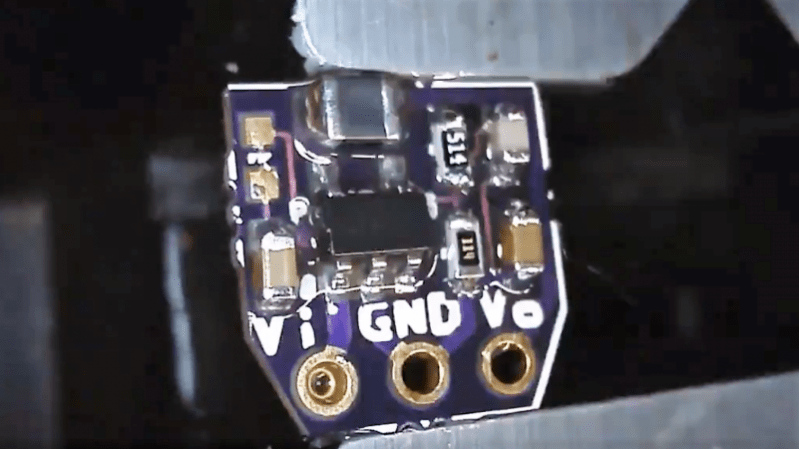
We’re suckers for miniaturization projects. Stuff anything into a small enough package and you’ve probably got our attention. Make that something both tiny and useful, like this 5-volt to 3.3-volt converter in a TO-220 sized package, and that’s something to get excited about. It’s a switch mode power supply that takes the same space as a traditional linear regulator.
Granted, the heavy lifting in [Kevin Hubbard]’s diminutive buck converter is done by a PAM2305 DC-DC step-down converter chip which needs only a few supporting components. But the engineering [Kevin] put into this to squeeze everything onto a scrap of PCB 9-mm on a side is impressive. The largest passive on the board is the inductor in 0805. Everything else is in 0603, so you’ll be putting your SMD soldering skills to the test if you decide to make this. Check the video after the break for a speedrun through the hand soldering process.
The total BOM including the open-source PCB only runs a buck or two, and the end result is a supply with steady 750-mA output that can handle a 1-A surge for five seconds. We wonder if a small heatsink tab might not help that; along with some black epoxy potting, it would at least complete the TO-220 look.
[Kevin]’s Black Mesa Labs has a history of turning out interesting projects, from a legit video card for Arduino to a 100-watt hotplate for reflow work that’s the size of a silver dollar. We’re looking forward to whatever’s next — assuming we can see it.


Man I still feel weird when people say 0603 parts are hard to solder…then i remember I install smaller components by hand for a living! Awesome little project tho. Gotta love these things :D
Eh, they really aren’t that hard if you have hand-eye coordination. I do not solder regularly (though an EE), but when I do, 0603s aren’t that difficult. 0402s are where it really gets dicey.
We have mostly 0201s on our most recent boards.
But hopefully you do not have to hand solder them. I see 0603 as quite easy, 0402 as doable, but best under a good microscope and 0201 I can barely see on a finished PCB. I could probably solder them under the microscope with good tools.
The real issue here is having a solder mask or not. Of course assuming a steady hand and good eyesight or adecuate optical gain.
Without solder mask 0603 approaches the width of the tracks for most homebrewed pcbs and the solder flows everywhere and joints get ugly.
I don’t like 0402 but mostly because many aren’t even marked.
Sharp tweezers help dramatically.
With the info, the IC could be changed to one that has different input and output limit. Looked at Digikey, TSOT-23-5 package that fits this goes up to 5.5v input max, 5v output max.
No 9v battery to 5v Arduino without changing the little board but it is still very useful.
If there is enough interest, I will look at doing a wide voltage range variant. I’m looking at this part https://www.digikey.com/product-detail/en/rohm-semiconductor/BD9C301FJ-E2/846-1117-1-ND/4022638 . My requirements are no external diode and small 0805 chip inductor ( 2.2uH – 4.7uH ). This Rohm BD9C301FJ fits both those requirements and has a wide 5V to 18V input range and 1V to 12V output range. Looks pretty nice on the surface. $1.70 in a SOIC8 package.
+1
+1
Just about finished. I want to add one more resistor and possible a ground ring on top side. See pictures here: https://twitter.com/bml_khubbard/status/973922256890941440
Here is link for a 3A with wide input and output voltage ranges. This has not been built yet, but making available early for anyone interested. https://oshpark.com/shared_projects/lAwfmKMT
Why bother when you can get a CUI V7803W for pretty cheap that will take up to 72V in? Or a Murata OKI for less that can take up to 35V in? This is a great project for learning, but for actual circuit construction, there already are fantastic dcdc converters out there that are drop in replacements for linears that are to220 sized…
Price and size are two standouts. The CUI is a massively bulky thing – good luck fitting it where a 780x would be used (plus it is good for a mere 500mA, and that’ll set you back US$10 at q1). The Murata OKI-78SR-3.3/1.5-W36-C is more compact than the CUI, and cheaper at US$4.30, but both parts suffer from a pretty significant dropout – CUI is 9-72V in, and the Murata is 7-36. The CUI part would be borderline useful with a 9V battery as input (or certainly after the battery drains a bit), and flat-out *neither* would be suitable if you were trying to buck a 5V supply to 3V3 (say because you already have a 5V rail, but need a bit of 3V3 love).
If you were designing a product for production, surely the switchmode circuit would be part of the PCB design and not implemented as a TO220 substitute. However, when prototyping a design, it can be very handy to have the supply as a plug-in module to experiment with, so if these are the parts you’d be using on PCB integrated switchmode, why not use them for a prototype supply?
So, what is the white paper being used for when soldering?
“It happened so fast, Officer, I’m not quite sure what happened!”
The white paper is actually the tape holding the SMD parts.
Thanks!
To get more power, you need a bigger inductor, a bigger heat sink is not going to help.
Correct. But also note that the inductor must have very low DCR to get any decent efficiency. Otherwise, for this voltage range and considering noise issues, not able to discern the advantage over a decent LDO linear regulator.
What exactly is the point of this fun little project? If it needs to be small, i’ll just go for one of the complete modules that offer the same output power in a micro package. Something like the TPS82150 in a 3.0x 2.8×1.5-mm package, 3V to 17V Input range and 1A continuous output current for example.
As for other DCDC converters in a TO220 package, there are a LOT of options already flooding the market from a ton of manufacturers, so if you don’t have some very exotic needs, you can just get some tested off the shelve products. (If you just need one, or very few for a project, remember to ask for samples ;) )
I have been using these for ages and 7 to 36 volts input 3.3 out. https://www.digikey.com/product-detail/en/murata-power-solutions-inc/OKI-78SR-3.3-1.5-W36-C/811-2195-5-ND/2259780
It was a $0.50 test board to evaluate a switcher solution for my Spartan7 FPGA design ( https://twitter.com/bml_khubbard/status/972970501541830656 ) . Final design is a 4-layer $60 fab, so I wanted to make sure the switcher design was sound and not a risk item for the FPGA design. After the fact, I just thought it’d be a fun little OSH kit project for people wanting to solder up their own power supplies for $2 ( vs $5 for off the shelf units ).
OK, that makes sense. But why would you pay 5$ for an off the shelve product? Look at the CUI VXO7803-500 for example. 2.4$ if ordered in single units from Mouser, all it needs are some input and output caps on the target board (where they should be placed anyway) adding a few cents more.
That’s an awesome price on the VXO7803-500. For my FPGA design I am bucking 5V down to 1V, plus I can’t use a thru hole design like this. My TO-220 design is just a test board that makes for an interesting DIY kit. Only advantage over an off the shelf product is the ability to hard select your output voltage. 3V was just a common example.
I use the TI TPS62160 switchmode IC for my own designs. Good for up to 17Vin, and programmable (with feedback resistor) for various output voltages, 1A of power, high switching frequency, and runs to Vin=Vout. Sports other features like EN and power good which are useful in a sequenced power supply config. Change the value of one resistor in the BOM, and I have a 3V3 or a 5V switchmode (or any of a number of other voltages I don’t commonly use).
At the beginning of this year, I laid out and fabbed a bunch of these in a TO220 sized adapter 8.24 x 12.53mm PCB. Cost was just $0.75 per set of 3 (of the PCBs – the other components are a bit more). Just the ticket for breadboarding, or populating a socket in someone else’s design that expects a linreg.
The TI part isn’t the cheapest option of course, but I have them and all the other support components on hand (including wire wound SMD inductors). You stick with what you know and trust.
I neglected to mention that TI has some fixed output variations on this IC (3V3 and 5V) that reduce the external parts count slightly. However, for the cost of the IC, I much prefer having a bunch of something I can adjust with a pair of resistors (and I’ve selected resistor values so that one of those is a bog-standard 100K, for both the 3V3 and 5V implementations).
The TPS62150 and TP62160 are very similar parts, not typos.
I understand designing and building something for fun or education but versions of these have been available for years, and for not a lot of money.
Yes – this one from Digikey for fixed 3.3V is especially nice and only $4 https://www.digikey.com/product-detail/en/murata-power-solutions-inc/OKI-78SR-3.3-1.5-W36-C/811-2195-5-ND/2259780. I can’t use a thru-hole solution for my FPGA board design however, so I designed my own single sided surface mount only layout. The BML DC/DC “Kit” is for the DIY crowd and as an educational platform. Select your R1 and R2 resistor values and get any voltage from 1.0V to 5.0V out after some fun 0603 soldering.
The speed-up capacitor in the feedback network should be bypassing the high resistor in the voltage divider – not the bottom resistor. In the reference circuit the capacitor is placed there to increse the gain above a certain frequency. In the current configuration the feedback circuit attenuates high frequency components.
You are correct. The 100pF cap is placed incorrectly on the PCB layout. It is connected to GND when it should be connected to Vout. Gerbers will be updated within 24 hours and new Shared Project uploaded to OSH-Park. Thank you.
100pF capacitor has been fixed. New Shared Project is available here https://oshpark.com/shared_projects/JgPScWaB
I am be a bit wary about the EMI compliance of such a thing, not even saying off-the-shelf parts do the same for less money, and have certified EMI compliance.
Then there is this need some people have, keep inventing some round thing with an axle they name a wheel, that can be a good thing to learn a lot, but in this case, the only “performance” is to squeeze components on a small board.
While this low-hanging fruit and probably EMI poisoned seems likely tasteless to most of us, it looked juicy enough that [Dan] picked it and regurgitated it here … go figure!
I have been using little buck boards from China for a while now. They are adjustable with a very small but oddly easy to tweak trim pot. They have a very wide input and output span. They are in the 90% efficiency range at 5v to 3.3v and they are rated at at last an amp. Oh, and they are off the shelf 10 for $5,
Before I got them I had pondered replacing the pots with fixed resistors but after using them for a few things now, they are actually very good as-is. If I were to do say an automotive project or something else subject to high vibration I might consider replacing the pot, but I have not felt the need to do that yet..