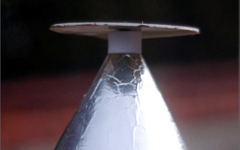
Antennas are a tricky thing, most of them have a fairly narrow range of frequencies where they work well. But there are a few designs that can be very broadband, such as the discone antenna. If you haven’t seen one before, the antenna looks like — well — a disk and a cone. There are lots of ways to make one, but [mkarliner] used a 3D printer and some aluminum tape to create one and was nice enough to share the plans with the Internet.
As built, the antenna works from 400 MHz and up, so it can cover some ham bands and ADS-B frequencies. The plastic parts act as an anchor and allow for coax routing. In addition, the printed parts can hold a one-inch mast for mounting.
Generally, a discone will have a frequency range ratio of at least 10:1. That means if the lower limit is 400 MHz, you can expect the antenna to work well up to around 4 GHz. The antenna dates back to 1945 when [Armig G. Kandoian] received a patent on the design. If you want to learn more about the theory behind this antenna, you might enjoy the video, below.
You often see high-frequency discones made of solid metal, or — in this case — tape. However, at lower frequencies where the antenna becomes large, it is more common to see the surfaces approximated by wires which reduces cost, weight, and wind loading.
As an example, we looked at an antenna made from garden wire. Perhaps the opposite of a discone is a loop antenna which works only on a very narrow range of frequencies.


A long long time ago, in a city about 800 miles away, I worked at a Radio Shack. We sold discone antennae as “scanner antennas” because of their broadband nature. Now I know why :)
I wonder what bizarre antenna a DeeplikeAI would come up given the controls of cad/cam driving a multimaterial laser sinterer loaded with dielectric powders.
You mean like the “Evolved antenna” used by NASA on the ST5 spacecraft, generated by a genetic algorithm.
https://upload.wikimedia.org/wikipedia/commons/f/ff/St_5-xband-antenna.jpg
Amazing what one can do with a paperclip. :-p
you should see what they can do with a safety-pin
I will admit that is what it looks like but, if you read what they actually did it is totally amazing, the boundary criteria for the evolution was “The antenna must have a voltage standing wave ratio (VSWR) of under 1.2 at the transmit frequency (8470 MHz) and under 1.5 at the receive frequency (7209.125 MHz). At both the transmit and receive frequencies the input impedance should be 50 Ω. The antenna was restricted in shape to a mass of under 165 g, and to fit in a cylinder of height and diameter of 15.24 cm.”
(ref: The American Institute of Aeronautics and Astronautics paper called “Automated Antenna Design with Evolutionary Algorithms” by Gregory S. Hornby, Al Globus, Derek S. Linden and Jason D. Lohn )
The first few iterations looked totally crazy by comparison to the final design:
https://www.researchgate.net/profile/Greg_Hornby/publication/220306511/figure/fig4/AS:277530117459975@1443179744980/Photographs-of-prototype-evolved-antennas-a-ST5-3-10-and-b-ST5-4W-03-A-color.png
Great post Truth :-)
Genetic algorithms are being applied to many disciplines including
psychology in its intersection with philosophy and theoretical physics
and at more rarefied levels too, social sciences and profiling too.
Of course this has nothing to do with the most recent theoretical
physics posit for which there is a foundation that space-time and gravity
is a merely emergent aspect from a base of entanglement variations ;-)
ie space-time is far more like a projection from a more fundamental physics
property and touched on by this short series of lectures by Nima Arkani-Hamid
https://www.youtube.com/watch?v=SWWBuHszyD8
So from a few combinatorial aspects we are in something akin to a
Matrix like simulation but, far more intimate than, so far, has ever considered
with perhaps the tenuous beginning of an Experimental Method to approach
the field along with “practical” phenomenology theoretical physics along
with the development of even more almost mystical intensely abstract math(s)…
I feel like this is one of my guiding principles. (Probably most HaD readers, too.)
Don’t forget the many various fractal antennas that lots universities seem to be developing…
My piece of this planet is about 6 acres, I don’t have an ol’ lady to aggravate, as long as don’t make a lot of noise or create a stink the neighbors don’t care what I do; so this ol’ man would love to try a 80 M. discone antenna. This being the Kansas High Plains the Wind is always an issue. However I think with additional poles the disk structure could be constructed to survive. Only if I had the required disposable income.
See if you can find an old Titan Missile site. They have Discone antennas that operate into HF.
http://www.titanmissilemuseum.org/ham-radio-operators
Well that is just very cool indeed! Would love to get a chance to visit that museum, and not just for the giant discone.
It is cool. Kind of creepy when you think about the use/design of it, but well worth seeing if you are in the area. There is an airplane museum associated with it as well: http://www.pimaair.org/
Thanks for this!!! Was literally just there yesterday and wondering what that “antenna looking thing” next to the parking lot was for since it wasn’t mentioned during the tour; isn’t really inside the missile complex perimeter; and we didn’t find an explanation inside, but could have missed it while wrangling the kids. Awesome place to visit for other things too, e.g. the silo had three separate backup antenna and motion sensing radar around the silo cover.
I also didn’t realize the same base foundation ran it and Pima Air, but clear as dayy on their website. Anyone that can should definitely hit both. My favorites at the air museum are the SR71 (http://www.pimaair.org/aircraft-by-name/item/blackbird) and the “Super Guppy” (http://www.pimaair.org/aircraft-by-name/item/super-guppy) that carried sections of the Saturn boosters, internally.
My favorite at the Pima air Museum is the cut away demo of the 36 cylinder radial engine. Push the button and see all the bits move. I can look at that thing every trip. Imagine designing something of that complexity without CAD and the materials science of the 1940’s!
Lots of cool stuff there though.
The skirt doesn’t have to be solid, usually they are legs forming the skirt and disc to eliminate the wind loading that a solid cone design generates.
I used a 40mhz-4Gz tx/rx commercial discone for my ham shack for a few years, and yeah my slim jim j match dipole and other stuff I used to make myself for the fun of it worked slight better at the frequency it was made for, for a general antenna the commercial all band all frequency discone was really good. Height helped it a lot I guess as it was way up on a pole.
With 6 acres you could probably set up a full size wire dipole for 80m and work groundwave over most of your country with a few watts erp :)
You could try ‘chicken wire’ for the conical section…
For tbe disc, any fairly thin materail(metal) should siffice.
Study commercial designs, and modify them to suit your frequency usage.
The discone antennas I’ve seen so far suffer from two problems:
– their gain is worse than a simple dipole or groundplane antenna
– they don’t perform well at frequencies above ~50MHz
So unless you really need the wide bandwidth, use something else.
@Cyk,
“So unless you really need the wide bandwidth, use something else.”
Yes you are correct.
“The discone antennas I’ve seen so far suffer from two problems:
– their gain is worse than a simple dipole or groundplane antenna
– they don’t perform well at frequencies above ~50MHz”
No, you are wrong. Don’t generalize like this. You obviously do not understand Antenna Theory.
It’s a pretty universal concept that the more general purpose you make a tool (or a person) the worse it is at any specific given task. Conversely the more specialized the better it is at one specific task.
This principal applies to antennas just as well as everything else. But… if you want to have a lot of bands then individual lower-bandwidth antennas for each one can be impractical. If your hobby is to get on some specific ham band and talk to your established group of friends then sure, a discone would be a bad choice. If your hobby is radio in general and you want to tune around all over the place just to find what is out there then a discone would be a great choice for you.