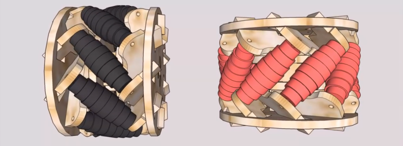
For the budding roboticist, omniwheels might be the next step in design patterns from your everyday “getting-started” robot kits. These wheels consist of tiny rollers that sit on the perimeter of the wheel and enable the wheel to freely slide laterally. With independent motor control of each wheel, a platform can freely locomote sideways by sliding on the rollers. You might think: “a wheel made of wheels? That sounds pricey…”–and you’d be right! Fear not, though; the folks at [Incubhacker] in Belgium have you covered with a laser-cut design that’s one-click away from landing on your workbench.
For anyone who’s tried to reliably mate flat laser-cut parts at an angle, we can tell you it’s no easy feat. The design here triumphs as both simple and reliable. Not only do they solve this problem elegantly, they also manage to create a design that will bear the load of a robot chassis that will travel with it. Laser-cut designs also usually suffer from a poor range of material options. Here the actual rollers need a bit more grip than what the plywood can provide. They also solve this problem effectively as well too, relying on heat-shrink tubing to provide the traction expected from a conventional wheel.
In the video below, [Incubhacker] takes you through the step-by process of making your own come to life. We’ve certainly seen some impressive laser-cut omniwheels in the past, but we like the simplicity of design combined with the composition of parts that probably already live on our workbenches.


I thought that heat shrink tubing has LESS traction than plywood.
Traction for what?
If anyone else is confused as to what in the heck this is: https://youtu.be/SNGLovxtgDI?t=434
Mecanum wheels still need friction in one direction, this is called traction in tires, they can roll but do not slide sideways. In mecanum small wheels are rotated, but they still need traction in their rotation direction.
Thanks for article, it caused me to do a search on Thingiverse for MECANUM and found 86 projects that you can 3D print MECANUM setup. As a mentor of a FIRST robotics team we built one of the first MECANUM robots, it was awesome. I also built a smaller one for a contest. MECANUM wheels are fun to play with. Being able to 3D print one brings cost way down.
I like the idea of using heat shrink as an impromptu tire tread.
Self-vulcanizing rubber tape could give more traction.
What is the purpose of the small and medium size disks on a hard surface? Only the largest disks seem to contact the floor. If the device is not expected to work on sand or in water, could the fabrication be simplified to large disks and long spacers?
I’m no expert on this, but I think the tapered parts are on swiveling mountings on each side. Depending on the motion of the wheel it may have more or less friction causing it to move in more directions compared to a normal wheel.
Take a look at the left and right edges of the Red wheel in the banner image.
The curve is there to maintain contact across the entire sub-wheel as the hub rotates.
Ah. The disks of differing size are used to approximate a spindle shape. Thanks
Interesting design for something that’s not taking a lot of load, or flexing.
The design looks great and I am about to start cutting it but can anyone link me to arduino code to drive it