If your Arduino runs out of I/O lines, you can always add one of the several I/O expander chips that takes a serial interface to set its several pins. Or perhaps you could buy something like an Arduino Mega, with its extra sockets to fulfil your needs. But what would you do if you really needed more pins, say a thousand of them? Perhaps [Brian Lough] has the answer. OK, full disclosure: If you really need a thousand, the video isn’t exactly for you, as he shows you how to add up to 992 PWM outputs. The chip he uses works with any microcontroller (the video shows an ESP8266), and we suppose you could use two daisy chains of them and break the 1,000 barrier handily.
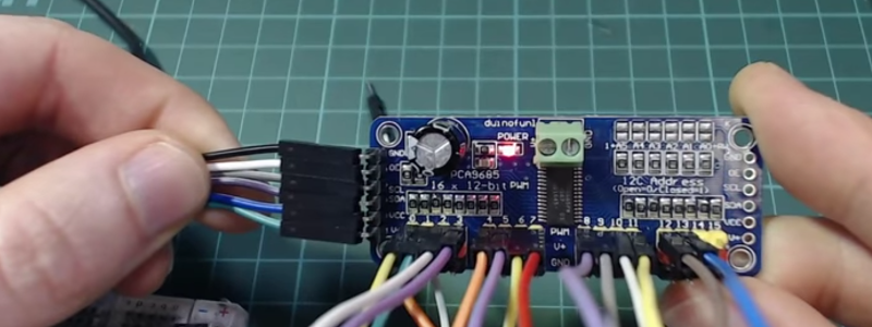
We like how short the video is (just two minutes; see below) as it gets right to the point. The PCA9685 chip gives you 16 12-bit PWM channels via an I2C interface. You can daisy chain up to 62 of the boards to get the 992 outputs promised.
[Brian] uses a cheap $2 breakout board that lets you set a 6-bit address, has a nice power connector and makes it easy to use the little surface mount device. Each of the 16 outputs on the board can have an independent duty cycle, but they do share a single output frequency. That means if you want to use some channels for low-frequency devices like motors and some for high-frequency devices like LEDs, you might have to spring $4 for two boards.
Over on Hackaday.io, we’ve seen these devices driving 128 vibration motors. The PCA9685 made us think of the time we rolled our own serial to PWM devices using an FPGA.


Short video, short article and an interesting topic.
Now I know what to grab next time I need more PWMs then I care to poke an oscilloscope probe or four at.
Thanks Alexander!
Actually, ATmega328P has two Output Compare pins named OC1A and OC1B which are connected to the 16-bit timer 1, so they can be used for 16-bit PWM. If it’s not possible using the Arduino IDE, then it’s the limitation of the IDE libraries, not the Uno board.
You can only set the TOP value up to 12 bit PWM – read the datasheet.
I read it again and you’re wrong:
“The Output Compare Registers contain a 16-bit value that is continuously compared with the counter value (TCNT1). A match can be used to generate an Output Compare interrupt, or to generate a waveform output on the OC1x pin.”
Is Arduino hard limited to one I2C connection or can one set up more than 1 I2C connection? Say 8 sets of I2C, each with max 62 devices?
you can bitbang i2c but it isn’t the most fun protocol to do that with, so any 2 digital input pins that supports hi-z and low output can do it technically, and the clock pin doesn’t even need to support hi-z from the master device unless there are slave devices that do things like clock-stretching.
The AVRs used by most Arduino boards have only a single hardware I2C interface. You could theoretically bit-bang additional interfaces, but it might get ugly if you had to update them all at the same time.
But I2C is a bus, designed to allow connection of multiple devices. Messages each contain an address (which is a lot of overhead in some circumstances, compared to SPI.)
However, I suspect that if you want to connect more than “a few” devices to an I2C bus, you have to start worrying about electrical parameters that are usually ignored (fanout, in particular, in its various aspects.)
I2C is originally quite slow (max. 100kHz) and if the device brings out 6 address pins, it is intended to be used in up 64 (or 62) pieces.
Just as a heads up, these seem to support a faster i2c, the examples in the Adafurit library set the speed to 400kHz I think
https://github.com/adafruit/Adafruit-PWM-Servo-Driver-Library/blob/master/examples/pwmtest/pwmtest.ino#L39
Use analog switch, for example CD4051 to multiplex clock lines of your various chains to single line of Arduino. Devices will ignore data line when there is no clock signal…
Or skip the analog mux and use proper I2C mux, like TCA9548A.
No, with any board that has more than one I2C-bus you can perfectly well use them all, and you could obviously also bitbang even more of them, if you really wanted to. By default the Wire-library, ie. the library that handles all the I2C-bus, only exposes one I2C-bus and most sensors-libraries and such have been written to only use that default one with no option for specifying another bus to use, though technically there’s nothing stopping you from modifying the relevant parts to make it use another bus instead.
Personally, whenever I write my own libraries, I like to make it easy to use a different bus than the default one.
I have no idea where they got the 62 figure from, because 2⁶ is 64, which gives you 1024 channels together. I know you can stack that many, because I use that chip since several years both in my robots and in the servo shields I sell on Tindie.
Obviously there are two reserved addresses (All Call and Reset).
Not quite. The addresses of the PCA9685 start at 0x40 (64), and the all-call address is 0x00 (0). There are 8 addresses reserved at the top of the range (for device ID and for 10-bit addressing), but if they respected that, you would have 56 devices, not 62, so it still doesn’t make any sense.
I got that number from the details in listing for the adafruit board this is cloned off.
https://www.adafruit.com/product/815
“You can even chain up 62 breakouts to control up to 992 PWM outputs”
One thing I like about this chip is that you can actually go from full off to full on, since both the turn on time and off are set independently. This means that you can use groups of 3 pins, connect the first two to a motor control bridge A/B channels (for direction control) and the 3rd pin to the bridge PWM control pin (for speed control). I built a simple wifi controllable 4wd robot with a esp8266 + PCA9685 + l298n + dc brushed motors and it works great.
Nice hack! Written it up? (tips@hackaday.com)
If you have a H-bridge DC motor driver with direction and enable(PWM) inputs, you tie the enable input high and put your PWM signal on the direction input instead.
What that does is, at 50/50 duty cycle your motor stands still because on average it’s seeing +-0 Volts across its terminals, and deviating from that will turn your motor one way or the other, with linearily increasing voltage. Single channel direction AND speed control.
As long as the PWM frequency is high enough, the motor won’t heat up at standstill because the coil impedance is too high to pass any current.
The reason I started looking at this chip again was that I wanted hardware PWM on an ESP8266, but at the same time I have a LED light strip running being controlled by a mosfet directly by an ESP8266 pin and I havent noticed a single flicker. Did you run into any issues with the software PWM?
Hi! Can you share the sketch and more details for this project! I need to do same thing.
I LOVE these PCA9685 boards, and have used dozens of them in my lighting projects (both LED and incandescent minilights). And, it’s really great to be able to buy them for under two bucks on AliExpress.
How do you handle the higher currents for the LEDs?
MOSFETs?
IGBTs, actually, with an optoisolator. When using 120V minilight strings rather than 12V LED strings, I add a bridge rectifier on the mains supply (no filtering is required). Very simple, very effective.
which distributor do you use in pegasus galaxy?
AliExpress has their own Stargate.
They don’t use Jump Points?
Like it and liked it. Short sweet simple. Although given the click bait title I was expecting some other psycho trying to use 992 outputs but nooooo.
Thanks! Ha, even to buy that many boards would be over $100 so I don’t think I’ll be trying it anytime soon!
” Although given the click bait title I was expecting some other psycho trying to use 992 outputs but nooooo.”
So, what are you trying to do with your 992 outputs?
B^)
Only up to 96 so far damnit. Latencies and power drops spoiling my fun. Not telling yet.
I believe that this board is a cheapo clone of Adafruit PCA9685 breakout (mentioned in the video). i think all outputs run on the same frequency and while you do get 12 bit PWM resolution, frequency range is limited to 2KHz. Not bad but isn’t as flexible a solution as i would like.
But what if you need 4096 PWM outputs?
https://www.elektormagazine.com/labs/the-resurrection-of-an-iconic-thinking-machine-cm-2
“That means if you want to use some channels for low-frequency devices like motors and some for high-frequency devices like LEDs”
I think you mixed them up boss. LEDs are typically modulated around 100 Hz but you may need close to 10-20 KHz for a motor.
I was thinking servo motors where the rate is quite slow.
To be fair I think LEDs can be modulated at a wide range of frequencies for PWM – certainly in all the applications I’ve worked on the LEDs were done in the kHz region (either to just avoid risk of seeing flickering or because it’s then easy to low-pass filter the signal to reduce transmitting a high-ish frequency signal to a front panel)
LEDs become less efficient at very high frequencies beacuse the junction capacitance starts leaking current.
What you’d ideally want to do is lowpass-filter the PWM and put it through a voltage-to-current converter.
You’d make a voltage controlled current regulator, kinda like so:
http://tinyurl.com/y82bkecw
You don’t really control servomotors with PWM because the duty cycle is around 1.5 – 2.5 ms every 20 ms. In other words, you can only use 1/20th of your resolution to turn the motor.
Even for 12 bits of PWM, you get less than 8 bits of actual resolution at the servo. Meanwhile, a software implementation using interrupts on a 8 MHz attiny will deliver you (theoretically) over 12 bits of resolution within that 1 ms control window.
A servo might not be accurate enough to use 12 bits, but using the PWM output of a microcontroller to control a servo is a hack.
Driving DC motors, you want the PWM frequency above 20 kHz so they wouldn’t whine, and driving LEDs you want it above 1000 Hz especially for RGB leds to avoid the rainbow effect. If you try to modulate a LED at 100 Hz you get a stroboscope – ten fingers in one hand when you wave your hand.
With normal pwm I agree. But my pak 8 was the same. You set the on time and off time separate so with the right time scale you can drive servos and people do it all the time.
I remember the crazy-expensive ($25) Pak-8! What a PITA that chip was. And they’re still trying to sell an equally-expensive, equally-limited version of it.
Actually they are EOL. In volume they were cheaper and we’re used in a surprising number of places in their day.
What is the pak 8?
For what I can find, it’s a rebadged microcontrolled (sold by you), that’s running some sort of software PWM implementation inside.
I was going by the learn guide that I reference at the end of the video that suggests 50Hz for servos and 1KHz for LEDs
Thanks for your additional info though!
How well does I2C work with 62 devices on the bus? I would assume that the parasitic capacitances would grow quite large, limiting bitrate.
You choose the pull-up resistors’ values based on the estimated capacitance and if you choose them wisely, it shouldn’t affect bitrates, AFAIK.
Also just a heads up, it seems like these have some pull ups included, I’m not great with reading schematics but they seem to have a 10K pull up resistor on each of the I2C pins
Nice little article, has a ring of “chip of the week” to it, a theme that in my mind could be a weekly issue of HaD if the devices found were interesting and useful.
Yeah, right? Send in your nominations to the tips line!
Well one will certainly not run out of chips to cover. There are entire volumes that cover this.
forget about the useful bit, interesting will do.BELLMAC-8?
Oh my, I haven’t heard about the BELLMAC-8 in almost 40 years.
Why no one talks about I²C Address translators?
http://www.analog.com/en/products/interface-isolation/i2c-smbus-bus-buffers-accelerators/ltc4316.html
With this device, you can double the PWM Ports
They are pretty cool, never heard of them before!
I once used a TLC5947 to PWM some LEDs. But I had to connect pull ups and MOSFETs to the outputs as I needed more current for LED strips at the outputs (8*RGB).
I got excited, because I need 16 PWM (at least) for a project I’m working on. Unfortunately, I need PWM in the 100 kHz range, and it looks like these top out between 1.6 and 2. Anybody know of something higher?
Look at the Teensy 3.5 or 3.6 [pjrc.com].