Converting A B&W Enlarger For Colour Analog Photo Printing

[Koraks tinkers] was gifted a gargantuan photographic enlarger, a Durst Laborator 138 s, which is a unit designed specifically for black and white usage only. This was not good enough for [Koraks] so down the rabbit hole of conversion to colour we go! The moral of the story is this: if you can’t find it, build it. The hacker mentality. After wasting time and effort trying to source a period colour head for the thing, [Koraks] did the decent thing and converted what was already in front of them.

A hacked Chinese-sourced COB array. This is no use.

Now, if you’re thinking this process is simply a matter of ripping out the tungsten bulb and sticking a high-power RGB array in there, then you’re going to be disappointed! You see, colour photography of the era — specifically the RA4 process in this case — requires careful colour calibration and is heavily biased towards the red end of the visible spectrum, due to the colour curve of those tungsten bulbs we touched upon earlier.

Attempt 2: With a heavy bias towards the red end of the spectrum

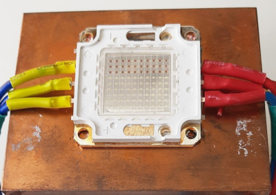
The first attempt at using an off-the-shelf COB array was a bust — it simply wasn’t bright enough once the light had passed through the diffuser plate, and the light path losses were too high to expose the RA4 paper sufficiently, especially at the red end of the spectrum. Quite simply this is due to the reduced energy of red photons (compared to blue) making the desired chemical reaction rate too low. The solution is more power.

Another issue that quickly raised itself was that 8-bits of PWM control of the RGB components was inadequate since the ratio of blue to red required was so skewed, that only a few effective bits of blue channel control were usable, and that was far too granular to get the necessary accuracy.

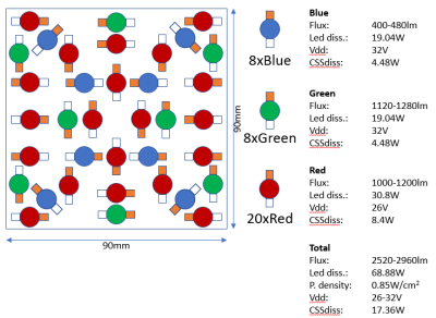
[Koraks’] approach was to custom build an LED array with twenty red 3W LEDs and eight each of the green and blue devices. 12-bits of PWM resolution was delivered via a PCA9685 PWM controller, that also handily controlled the cooling fans. The whole thing was hooked up to an Arduino Nano, with an MCP23016 expander board performing the duty of interfacing the rotary encoders and trigger footswitch. In fact, several iterations of the LED array have been constructed and this four-part blog series (Part1, Part2, Part3, Part4) lays out the whole story in all its gory detail for your entertainment. Enjoy!

COB LED arrays are pretty nifty, checkout turning them into 7-segment displays, just because. If all you want is raw power, we reckon that 100W “should be enough for anyone…”

Thanks [macsimski] for the tip!

Update: Corrected the article header from ‘exposer head’ to ‘enlarger’ for clarity at the request of the project author.

Fetch ferrofluid display

Ferrofluid Display Gets New, Better Driver Circuitry

In 2019 [Simen] and [Amud], two students from the University of Oslo, set out to design a unique open-source display. The result was Fetch, a display that uses electromagnets to suspend ferrofluid on 252 “pixels” across the screen. After some delays due to COVID, they have recently unveiled version 2.0 of the display on their project’s page.

While the duo managed to overcome the mechanical challenges associated with using ferrofluids fairly easily, they were quickly bottlenecked by their electronics. The use of electromagnets holding up a liquid presented a unique challenge; the magnets could not be switched off, even for a millisecond, or else the “pixel” would fall down to the bottom of the screen. That immediately ruled out any sort of multiplexing and meant everything would have to be driven in parallel. As if that wasn’t already difficult enough to work around, the effect of having multiple electromagnets activated next to each other would change how the ferrofluid flows. This meant that the strength of each electromagnet would have to be adjusted based on what is currently being displayed, rather than just being on or off.

The mess of connections were not helped with the layout of the old driver boards shown here. The new design puts the connections closer to each individual electromagnet.

All of this, paired with other overhead like generating pulse-width modulation for the inputs, was just too much for a single microcontroller to handle. So, the pair set out to design a better version of their electronics that would offload a lot of the hard work. At the same time, they decided a bit of mechanical optimization was in order; they redesigned the boards to be longer and thinner, allowing them to fit cleanly behind the row of electromagnets they controlled.

The new boards feature a PCA9685 IC, which allows for the control of up to 16 channels of 12-bit PWM over i2C, perfect for the size of the display. Since this IC can’t source enough current to drive the electromagnets, it was paired with a ULN2803 Darlington Transistor Array, capable of delivering up to 500mA to each electromagnet.

With prototypes in hand (and a few bodge wires here and there), [Simen] and [Amud] had the new driver boards running beautifully, displaying text in a mesmerizing way that no ordinary display could match. Watch the video after the break for a demonstration of the new controllers in action, as well as a deeper dive into the process of developing them.

Want to learn more? Check out our previous article about Fetch! Or if you’re looking for another cool way to use ferrofluids, how about making it dance in a custom speaker!

Continue reading “Ferrofluid Display Gets New, Better Driver Circuitry”

Building This Mechanical Digital Clock Took Balls

In the neverending quest for unique ways to display the time, hackers will try just about anything. We’ve seen it all, or at least we thought we had, and then up popped this purely mechanical digital clock that uses nothing but steel balls to display the time. And we absolutely love it!

Click to embiggen (you’ll be glad you did)

One glimpse at the still images or the brief video below shows you exactly how [Eric Nguyen] managed to pull this off. Each segment of the display is made up of four 0.25″ (6.35 mm) steel balls, picked up and held in place by magnets behind the plain wood face of the clock. But the electromechanical complexity needed to accomplish that is the impressive part of the build. Each segment requires two servos, for a whopping 28 units plus one for the colon. Add to that the two heavy-duty servos needed to tilt the head and the four needed to lift the tray holding the steel balls, and the level of complexity is way up there. And yet, [Eric] still managed to make the interior, which is packed with a laser-cut acrylic skeleton, neat and presentable, as well he might since watching the insides work is pretty satisfying.

We love the level of craftsmanship and creativity on this build, congratulations to [Eric] on making his first Arduino build so hard to top. We’ve seen other mechanical digital displays before, but this one is really a work of art.

Continue reading “Building This Mechanical Digital Clock Took Balls”

This Barometer Looks Mighty Fine, Rain Or Shine

Mythological legend has it that Tempestas, the Roman goddess of storms and sudden weather, saved the consul Scipio when his fleet of ships got caught in a storm off of Corsica. In return, she demanded that a temple be dedicated to her.

[SephenDeVos]’ beautiful barometer, dubbed Tempestas II,  demands nothing of the viewer, but will likely command attention anyway because it looks so cool. If the weather is anything but clear and sunny, the appropriate sun-obscuring weather actor, be it clouds, more clouds, rain, or lightning will swing into place, blocking out the blue sky in layers, just like real life.

There’s a total of five weather-serving servos, and they’re all controlled by an Arduino Nano through a 16-channel PWM driver. The Nano gets the news from a BMP280 barometric pressure/temperature sensor and drives the servos accordingly.

Nine layers of nicely-decorated Plexiglas® hide the clouds and things in the wings while it’s nice outside. We totally love the way this looks —  it’s even pretty on the back, where the sun don’t shine. This one is new and ongoing, so it seems likely that [Sephen] will post the code before the sun sets on this project. In the meantime, check out the demo after the break.

We don’t see too many barometers builds around here — maybe there’s too much pressure. This one tells you to lay off the coffee when the pressure’s too low.

Continue reading “This Barometer Looks Mighty Fine, Rain Or Shine”

Little Lamp To Learn Longer Leaps

Reinforcement learning is a subset of machine learning where the machine is scored on their performance (“evaluation function”). Over the course of a training session, behavior that improved final score is positively reinforced gradually building towards an optimal solution. [Dheera Venkatraman] thought it would be fun to use reinforcement learning for making a little robot lamp move. But before that can happen, he had to build the hardware and prove its basic functionality with a manual test script.

Inspired by the hopping logo of Pixar Animation Studios, this particular form of locomotion has a few counterparts in the natural world. But hoppers of the natural world don’t take the shape of a Luxo lamp, making this project an interesting challenge. [Dheera] published all of his OpenSCAD files for this 3D-printed lamp so others could join in the fun. Inside the lamp head is a LED ring to illuminate where we expect a light bulb, while also leaving room in the center for a camera. Mechanical articulation servos are driven by a PCA9685 I2C PWM driver board, and he has written and released code to interface such boards with Robot Operating System (ROS) orchestrating our lamp’s features. This completes the underlying hardware components and associated software foundations for this robot lamp.

Once all the parts have been printed, electronics wired, and everything assembled, [Dheera] hacked together a simple “Hello World” script to verify his mechanical design is good enough to get started. The video embedded after the break was taken at OSH Park’s Bring-A-Hack afterparty to Maker Faire Bay Area 2019. This motion sequence was frantically hand-coded in 15 minutes, but these tentative baby hops will serve as a great baseline. Future hopping performance of control algorithms trained by reinforcement learning will show how far this lamp has grown from this humble “Hello World” hop.

[Dheera] had previously created the shadow clock and is no stranger to ROS, having created the ROS topic text visualization tool for debugging. We will be watching to see how robot Luxo will evolve, hopefully it doesn’t find a way to cheat! Want to play with reinforcement learning, but prefer wheeled robots? Here are a few options.

Continue reading “Little Lamp To Learn Longer Leaps”

A Word Clock, The Hard Way

We’ve all seen word clocks, and they’re great, but there are only so many ways to show the time in words. This word clock with 114 servos is the hard way to do it.

We’re not sure what [Moritz v. Sivers] was aiming for with this projection clock, but he certainly got it right. The basic idea is to project the characters needed to compose the time messages onto a translucent PVC screen, which could certainly have been accomplished with just a simple character mask and some LEDs. But for extra effect, [Moritz] mounted each character to a letterbox mounted over a Neopixel. The letterboxes are attached to a rack and pinion driven by a micro servo. The closer they get to the screen, the sharper the focus and the smaller the size of the character. Add in a little color changing and the time appears to float out from a jumbled, unfocused background. It’s quite eye-catching, and worth the 200+ hours of printing time it took to make all the parts. Complete build instructions are available, and a demo video is after the break.

We like pretty much any word clock – big, small, or even widescreen. This one really pushes all our buttons, though.

Continue reading “A Word Clock, The Hard Way”

Vintage Plotter Turned Fruit Spectrometer

Fruit can be a tricky thing: if you buy it ripe you’ll be racing against time to eat the pieces before they turn into a mushy mess, but if you buy the ones which are a bit before their prime it’s not always easy to tell when they’re ready to eat. Do you smell it? Squeeze it? Toss it on the counter to see if it bounces? In the end you forget about them and they go bad anyway. That’s why here at Hackaday we sustain ourselves with only collected rainwater and thermo-stabilized military rations.

But thankfully Cornell students [Christina Chang], [Michelle Feng], and [Russell Silva] have come up with a delightfully high-tech solution to this decidedly low-tech problem. Rather than rely on human senses to determine when a counter full of fruit has ripened, they propose an automated system which uses a motorized spectrometer to scan an arrangement of fruit. The device measures the fruit’s reflectance at 678 nm, which can be used to determine the surface concentration of chlorophyll-a; a prime indicator of ripeness.

If that sounds a bit above your pay grade, don’t worry. The students were able to build a functional prototype using a 1980’s era plotter, a Raspberry Pi, and a low-cost AS7263 NIR spectral sensor from SparkFun which just so happens to have a peak responsivity of 680 nm. The scanning is performed by a PIC32MX250F128B development board with an attached TFT LCD display so the results can be easily viewed. The Raspberry Pi is used in conjunction with a Adafruit PCA9685 I2C PWM driver to control the plotter’s stepper motors. The scanning and motor control could be done with the PIC32 alone, but to save time the students decided to use the Raspberry Pi to command the PCA9685 as that was what the documentation and software was readily available for.

To perform a scan, the stepper motors home the AS7263 sensor module, and then passes it under the fruit which is laying on a clear acrylic sheet. Moving the length of the acrylic sheet, the sensor is able to scan not only multiple pieces of fruit but the entirety of each piece; allowing it to determine for example if a section of a banana has already turned. The relative ripeness of the fruit is displayed to the user on the LCD display as a heatmap: the brighter the color the more ripe it is.

At the end of their paper, [Christina], [Michelle], and [Russell] note that while the scanner worked well there’s still room for improvement. A more scientific approach to calculating how ripe each fruit is would make the device more accurate and take out the guess work on the part of the end user, and issues with darker colored fruit could potentially be resolved with additional calibration.

While a spectrometer might sound like the kind of equipment that only exists in multi-million dollar research laboratories, we occasionally see projects like this which make the technology much more accessible. This year we saw a compact spectrometer in the Hackaday Prize, and going a bit farther back in time we even featured a roundup of some of the most impressive spectrometer builds on Hackaday.io.

Continue reading “Vintage Plotter Turned Fruit Spectrometer”