STL files are everywhere. When there’s something to 3D print, it’s probably going to be an STL. Which, as long as the model is good just as it is, is no trouble at all. But sooner or later there will be a model that isn’t quite right in some way and suddenly project progress hits a snag.
 When models interface with other physical things, those other components may not always be exactly as the designer expected. Being mindful about such potential inconsistencies during the design phase can help prevent problems, but it’s not always avoidable. The reason it’s a problem is because an STL file represents a solid model as a finished unit; it is not really intended to be rolled back into CAD programs for additional design changes.
STL files can be edited, but just like re-modeling a component from scratch, it can be a tricky process for those who don’t live and breathe this stuff. I’ll describe a few common issues related to STLs that can hold up getting that new project together, along with ways to deal with them. Thanks to 3D printing becoming much more commonplace, basic tools are within reach of even the least CAD-aware among us.
Adding Hardware Can be Tricky
The most common reason an STL file may be not quite right is a mechanical connection where some piece isn’t quite as the designer expected, so the 3D model that interfaces with it no longer fits.
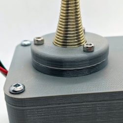
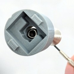
I ran into this issue recently when building my own version of a project called TWANG! which is a delightful one-dimensional dungeon crawler played on an LED strip, with a 3D printed enclosure and component housing. The joystick is a spring doorstop with the wide base secured by a retainer ring, and topped with a knob that contains an MPU-6050 accelerometer and gyro. I built mine by using this remix by [Bart Dring] but found that my hardware didn’t quite match the designer’s versions.
The ways in which the STLs were Not Quite Right are fairly typical examples. In order of increasing severity, they were:
- The version of the Arduino board I used had slightly different mounting hole locations. The enclosure still fit the board, but the mounting holes were not a match. No changes to the printed model were needed to deal with this minor issue.
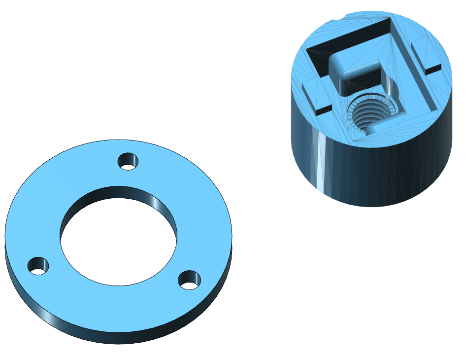
- Spring doorstops are identical in function, but not in shape. Mine all had bases that flared out earlier than the one the STL was designed for. This meant that the retainer ring sat too high up on the spring. This was fixed by adding an extra 4 mm spacer as a separate piece. I modeled this simple object from scratch to fix the issue.
- My spring doorstop also had a narrower top than the designer’s version. The joystick knob was nicely threaded to mate to a doorstop, but it was too big for mine. I fixed this by scaling only the threaded portion down to match while leaving the rest (which housed the MPU-6050 board) unchanged.
Basic Methods for Tweaking STLs
If an STL is not right because of a physical interface problem, there is usually only one thing really wrong with it. Either something is not quite in the right place, or is too large or too small, and the model can’t be used as-is. It is not possible to perform the usual CAD functions on an STL file to fix such issues, but there are still some things that are easy to do with STLs, even for novices:
- Cutting models into separate, smaller pieces
- Scaling pieces in one or more than one axis
- Merging smaller models into a larger one
- Somewhat less simple (but still accessible) are operations like subtracting one model’s shape from another, or keeping only the intersecting areas between two models.
These options can provide a workaround when the problem can’t be simply ignored or fixed with a bit of tool work.
Example: Resizing a Model
To deal with my spring and threaded hole mismatch, I first cut the model apart to isolate the threaded section. Then I resized the threaded section in x and y only, leaving z (height) unchanged. The thread pitch of the spring was good, it’s just the diameter of my spring was physically smaller than the one the designer expected. After the threaded portion was scaled correctly, I merged all the pieces back together.
I cut out a central cylinder containing the threaded portion with Autodesk’s 123D Design (now discontinued) but it would have also been possible to cut a square section out via a few straight cuts, using the same tools that are used to cut models into pieces to fit smaller print beds.
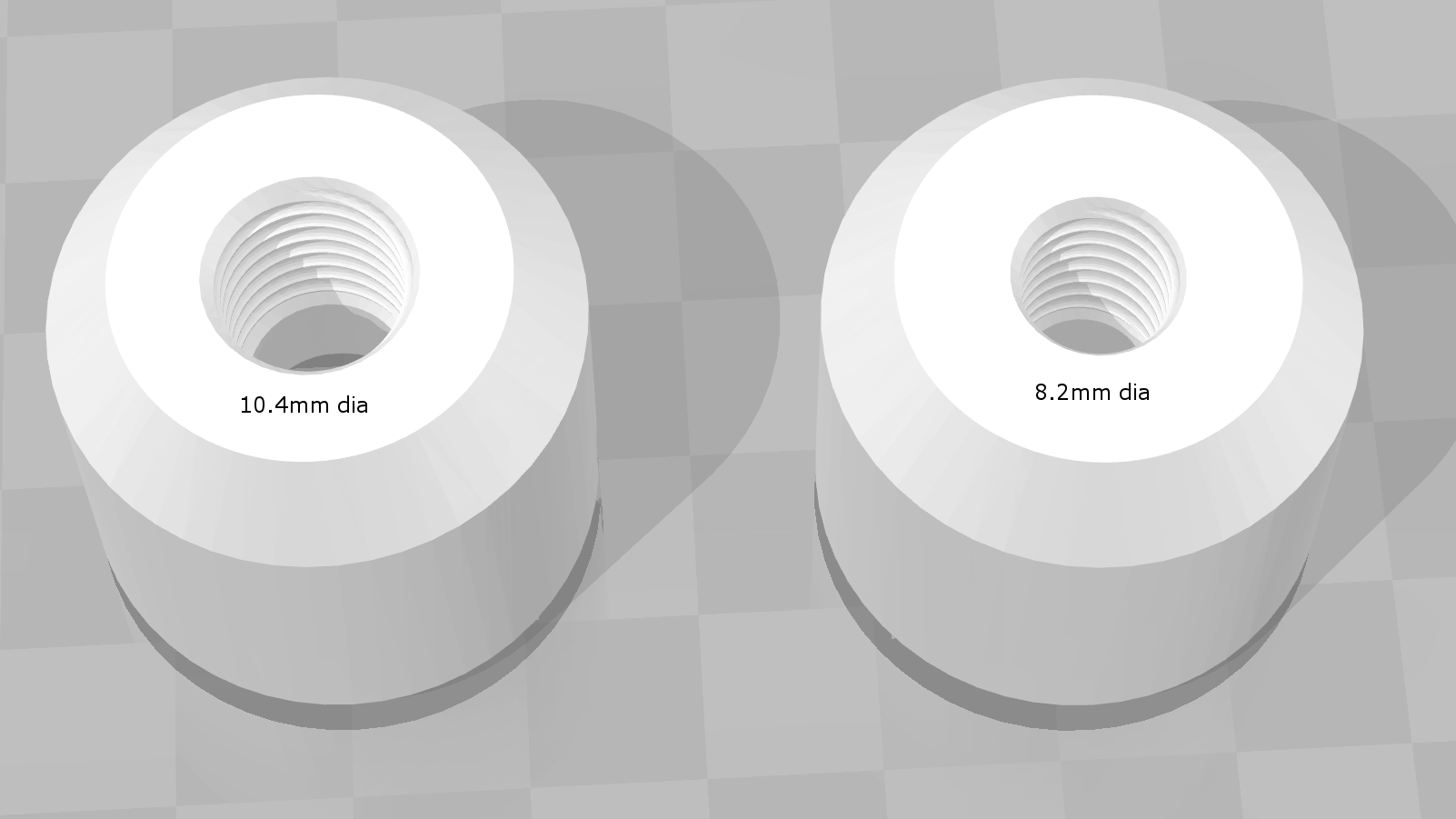
To determine the amount by which I needed to scale the threaded portion, I measured the (too-large) STL and found it to be 10.4 mm between the narrowest parts of the threads on the model. Then I measured my actual spring, and found that I’d need to bring that size down to 8.2 mm.
(diameter needed) / (diameter of source) = scale factor
8.2 / 10.4 = 0.79
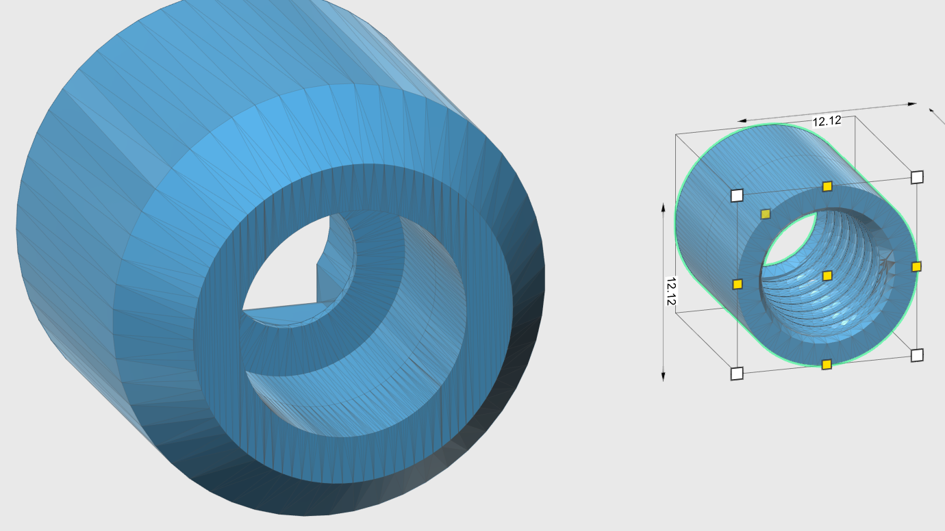 The cut-out section was 15.3 mm per side, and scaling it by a factor of 0.79 brought it down to 12.1 mm. The resulting threaded area diameter went from the original 10.4 mm to 8.2 mm, which would fit my spring. At this point, it would be possible to 3D print only the small section that was resized in order to physically test the fit.
Only one issue remained after resizing the threaded section: the cut-out part was now smaller, leaving a gap when it was re-inserted into the original model. One way to solve this is to model a small hollow cylinder slightly larger than needed to fill the gap, and merge all three models together. The other option is simply to lay the new, smaller threaded insert into the original model like an adapter, and merge the models together. Either way, the overlaps are obliterated and the new model has only the smaller threaded section.
Useful Software Tools
Different tools are good at different things, and while most programs have some interfaces that take getting used to, here are some useful and accessible options for manipulating STL files:
- Meshmixer can do many things, but in particular makes pinching and pushing areas of STL models as if they were made of clay very easy. Other powerful functions are a bit harder to use.
- Tinkercad is a web-based CAD tool with an accessible interface that can import STL files and treat them like any other object, as long as they aren’t too complex.
- Blender allows for advanced manipulation; one of the things Blender can do is select points on a model, then move only those points in a specific axis. It’s akin to a push/pull on a face and is a powerful tool for tweaking STLs, but like most CAD programs, it’s not really practical to just click around until you figure things out. Tutorials are available.
- 3D Builder by Microsoft (included in Windows 10) is making a big push to being useful for common operations. It has an intuitive measurement tool and is capable of performing many functions like splitting, merging, scaling, and even intersecting and subtracting models.
- Raise3D’s ideaMaker software is intended as an all-in-one control and slicing software for their line of 3D printers, but it can be used without a printer. I mention it because it includes an easy to use suite of tools for splitting, merging, scaling, and repairing STL files while also having an accessible interface. The orthographic view mode helps with precisely aligning and moving models.
- OpenSCAD is capable of importing STL files but it’s also not a typical CAD system; we covered what OpenSCAD is and how to use it in the past.
Helpful Practices for Designs
Sharing models via STL isn’t going away any time soon, but it helps to be mindful of the ways in which things may end up being not be quite right for someone down the road.
Just as people now regularly design models as separate parts that will 3D print more easily, so too is it helpful to make design decisions that try to allow for changes that are out of one’s control as a designer. Would a model still be useful if mounting hole locations changed? Could a user make fixes or adjustments with only a limited toolset? Is it possible to make the interfacing parts modular for easier adjustment?
What’s Your Method?
Having to go back to adjust an STL file can be an unexpected delay in a project, but it can sure beat needing to do a lot of manual rework as an alternative. Re-creating a 3D model of a part from scratch is always a possibility for those comfortable with modeling, but do you have your own tips or methods for addressing common misfits with STL files? What’s your favorite way to make it fit? Let us know in the comments!


Fusion360 can convert a mesh to a BRep which can then be modified as needed or even added into a completely different design. See: https://knowledge.autodesk.com/support/fusion-360/learn-explore/caas/sfdcarticles/sfdcarticles/How-to-Convert-a-Mesh-to-a-BRep-in-Fusion-360.html
Thanks for sharing a link directly to a how-to, that’s great and I’m checking that one out for sure!
(Fusion 360 also has a free license for hobbyists and startups, for anyone who doesn’t know)
But you’ve gotta pay for a Windows license, so it’s sort of a wash. :(
Not knocking Windows, here, just feeling left out as a longtime Linux-only person.
Your best CAD option in Linux is OnShape. I don’t know about its ability to modify STLs.
That’s been my experience as well.
Onshape can import STLs and use them as a geometry reference, but you can’t edit them or include them in a model.
Not really. You can get a win10 license in the $30 range now, and then can run Fusion 360 for free.
I like Linux for many things, but all this software has a steep learning curve and a stable, well supported OS is a real advantage.
Such as linux :)
Autodesk is developing a browser version of Fusion 360. It’s already available for free and does not require Windows. Of course it’s still missing some (more advanced) features but it is quite usable for most things. Here’s more info: https://www.autodesk.com/products/fusion-360/blog/fusion-360-in-a-browser-preview/
may I introduce you to our lord and savior HWIDGEN?
Thanks for the comment about the free license. At a surface level, it looked like it was only free for educators and students. Upon digging a little further I find:
https://www.autodesk.com/products/fusion-360/free-trial
“Are you a startup or hobbyist? You may qualify for free use.”
For some problems, Designspark Mechanical (free!) does a pretty good job at reverse engineering the surface model back into a solid. Since it is basically a freeform CAD tool, it’s very easy to drag/move features or faces around.
For more professional work, the “big brother” of Designspark Mechanical, Ansys Spaceclaim, has even more tools to reverse engineer STLs back into solid bodies and even fixes holes in the model, finds curves and stuff like that. (last time i checked, a Spaceclaim license costs around 2500€)
Fusion 360 is pretty good at converting surface models back into a BRep, at least if you don’t have something with more than 50k faces. But i’m not shure how well it handles faulty stuff (holes in the model), and as far as i know, there are no functions to allow you to find features like arcs and circles. Usually i just draw some sketches on top with the arcs/circles/splines to get the original shape back, then remove the old features of the STLs that i like to replace.
Yeah the problem with STL is you can not get back the original design intent for cylindrical objects with high degree of precision, like you point out. For most simple models its just faster to remodel it from scratch. The F360 BREP is still composed of triangular faces but you can delete them and F360 will kinda merge them in to a single face. The only problem with this approach is its tedious and sometimes doesn’t work.
After repeatedly running into the limits of Fusion 360, I bought Spaceclaim to convert 3D scans into solid geometry. You can definitely fit a cylinder solid to a selection (see video around 40 seconds in), you can fit circles to arcs, and you can snap solid geometry onto a surface. The mesh repair tools are insanely good.
https://www.youtube.com/watch?v=8BDoYRm9yf0
the language in this video is overblown marketingspeak, but just watch the tools to fit surfaces and primitives to scan data.
https://www.youtube.com/watch?v=Q2o12d6A16k
Spaceclaim is like the “best kept secret” in the solid modeling world. It has outsized capabilities, it’s cheaper than nearly every other option, and it handles scan data like a champ. The next step up, for STL and for scan data, is Geomagic Design X… and that’s $40k/license.
Fusion360 is my go-to modeler, but the reverse engineering tools are very primitive. I mean, I’ve never had a useful 3D scan come in at under 10K polygons. Most of my scans are around 100k-300K polys. Fusion can’t even import it. SpaceClaim doesn’t even flinch. SpaceClaim has paid for itself twice over in my prototyping shop.
Another method is to purposefully make a tight cylinder with no threads printed, then heat up your bolt over a gas stove and drive it right in. Just don’t tighten it until it’s cooled!
But I feel you, I have to modify STLs all the time. Do it in software with polygonal modeling tools, like blender as you mentioned. It’s not too bad once you get used to it. I use Maya because I’m one of those lucky people that lives and breathes this stuff as you say. Been making polygonal models professionally for a long time. In fact I feel bad for anyone who wants to modify my designs because they aren’t going to get a cad file. The polygonal model is the source file. It’s fine for my job, but it sucks for 3d printing and industrial design. I should fix that and start using CAD correctly, but I’m just so much faster at polygonal modeling.
So, is the diameter of your untapped bolt hole, half of the depth of the bolt threads? (to allow the plastic a space to squeeze into)
It can even be considerably smaller than the shank of the bolt. The melted plastic will get out of the way when it encounters the mechanical advantage of bolt threads. Possibly moving into the infill.
It’s not pretty, but the thermal tap keeps you from having to dial in tolerances so tightly. Which is pure laziness on my part.
Hah, I think I know what you mean. The phrase “when you have a hammer, every problem looks like a nail” kind of applies to this sort of work, doesn’t it? On one hand I use probably a half-dozen different tools for little bits here and there because everything is good at different things, but on the other hand I am probably really just sticking with what I know and “making do” more than I need to.
I often import STL files into Sketchup to adjust dimensions then export them back to STL. One of the main issues with this method is that rectangular faces will import as two triangular halves. Deleting the line that bisects the face on the diagonal will let Sketchup treat it as a single flat face that can be pushed/pulled or extruded.
This is my workflow, too. There are a few plugins that can automate the process of removing the extra edges.
I work in Maya to create my obj’s. There are 2 things I have noticed when importing models into my slicer(makerbotdesktop). Faces with more than 4 sides and non cohesive normals will cause errors with the slicer. Before I export obj’s, I triangulate and quadrangulate my models and make sure normals are facing the same way.
It really depends on how many times im going to use the part or a derivative of the part, It also depends on how complex the part is. If it is a simple part to be used multiple times then i import the stl file and use it as a reference to remodel the entire thing. If it is only to be used once then i import it and directly change the features that i need to change, this usually happens by merging the STL solid with a solid of my own drawing to achieve a face which to work off of (as stl files are usually just triangles) and then work from there. There is of course a gradient between the two extremes but what is important is the method (not the tools) as the tools all will eventually do the same thing just with different commands.
You can tell there is a huge mindset difference between professional engineers/designers and hobbyist by comparing grabcad or mcmaster carr to thingiverse. The majority of models on grabcad are STEP files with the native cad package file a MUCH BETTER way to share design data. While on thingiverse and a lot of hobbyist projects its STL and nothing else.
Why use a STEP file? Because its a “Standard for the Exchange of Product model data”, universally accepted by 3D Cad programs, easy to modify, easy to measure, and just over all better then STL. McMaster-Carr has 7 different cad formats to download models of hardware from their site and not one of those is STL. Why because no working professional would waste their time with an STL file.
It seems like hobbyist just fell into STL files as the their default file format because of the 3d printers, there is no good reason to do that. All good CAD packages can convert an STEP file into an STL, it takes no time to do that at all. I really hope people put out STEP files instead of or along with their STL files. Part of being open source is that source is supposed to be as easy to modify and contribute, STL are anything but easy to modify.
Kind of the difference quality-wise between live and MP3.
Kind of. Live only insinuates the setting of the performance while MP3 is a file format, which can vary considerably in bit rate and overall “quality”. Bootleg live recordings tend to be high quality though and MP3 is a lossy format to a degree.
A better though still incomplete analogy would be the difference between BMP and JPG file formats.
An even better one would be open source versus a binary executable. The STL is basically a binary “executable” with the real “design intent” and parametric values completely stripped away. Versus something like a native CAD file being more akin to source code that you can modify and then recompile as many times needed.
Don’t get me started on the wrinkle that cloud computing formats place on this already somewhat stretched analogy.
+1
Absolutely STl is like Binary executable not the source code.
Some users on Thingiverse include source files. What can we as a community do to encourage more of this?
Better analogy – rasterising a vector file. Very easy to go Vector to Raster, extremely hard to go Raster to Vector (and preserve any sort of integrety).
I have a question maybe you can help answer: since STEP files are non-proprietary and portable, why aren’t they accepted more in 3D printing related programs and services?
A quick check shows that Thinigiverse does not accept STEP files (oops, actually they do – it’s just not listed in their accepted file format list.) My Slicer (for 3D printing) doesn’t import them. The uploader for 3dhubs DOES accept them (which is nice but atypical.) It’s a non-proprietary format, why isn’t it used more across these 3D printing focused platforms and tools?
Thingiverse does have STEP files there is even a tag for STEP files. Some people do post STEP files , unfortunately not every one. Having used professional metal sls services they specifically did not want STL and wanted step files. Most machine shops want nothing to do with a STL. It seems that everything geared towards hobbyist and consumers revolves around STL which probably because that is what hobbyist know. While professional services are geared to native cad file formats or step files.
STL stands for Stereo-lithography originally created in 1987 by 3d systems for the very first 3d printers. Its a file format that was developed to aid making slicing possible, its format specific to 3d printers. That is why all slicers look for it as an input, its how the industry developed. It was never designed as CAD file format.
STL files are a mesh triangular faces which is an approximation of the original cad file. NO cad program I know of works natevily in STL all of them have to convert the original design file into an STL in order to send to a 3d printer. STL is file format specific to 3D printing, great for slicers and making G-code but terrible for design work and modification. Technically STL is not even the “source code” for a mechanical design , its a compiled version of the source code, the native file format. While STL was designed to make slicing possible it was not designed to as means of export the design of part in meaningful way. STEP was designed specifically to allow design data to be passed around in an accurate and easy way, between CAD packages.
If you want people to be able to modify your files easily in a CAD program then export an STEP file and save us all the hassle of remodeling your STL.
Are STL files actually great for slicers? It seems like slicing a surface mesh would be considerably more awkward than slicing a solid model. I always assumed (and daid303 below states) that the real impediment to using STEP files is the complexity of the file format itself.
The 3D printing ecosystem doesn’t use STEP files. For whatever reason, a long time ago someone decided that STL was the thing that slicers were going to interpret. The slicers went with STL, so the 3D print sharing sites went with it. GrabCAD and other “professional” sharing sites are not aimed only at 3D printing, so they host other formats.
Cloud based CAD like OnSHape and Fusion360, can provide sharable links to the design files which can be exported from the CAD page as STL, OBJ (which some slicers can use), STEP, or other formats.
I have stopped posting designs to Thingiverse and Youmagine in favor of linking the designs directly from my blog. I can be as descriptive as I want in the more flexible format of the blog and don’t have to send the traffic to other sites. If I want to let the design file go, I can share the Fusion360 link, other wise I can link to the STL file in google drive.
I can explain the reason. (I made Cura)
A step file is a whole lot more complex to read then an stl. Reading an STL file is so easy that I can write a reader in a hour. Step files however, the only open-source application that can sort of read those is FreeCAD, and even that fails from time to time. There are no easy to use libraries to read an STEP file beyond the basic format (but that does not give a 3D model, only the raw data)
OBJ files are also easy to read. I tried reading STEP files, but I gave up on that attempt.
So the end reason is, effort. Nobody has done the effort to make a working STEP reader. And the required effort is high. Extremely high amount of effort compared to STL.
Thanks for Cura
I hadn’t realized there was such a gulf between the formats. Thank you for sharing that explanation, that makes a lot of sense.
And yet every Commercial piece of CAD software I ever used can do it. Also Onshape and Fusion 360 are free to hobbyist. This goes back to what said earlier that STL where developed for 3D printers not for CAD work.
I don’t want to encourage slop and poor software, but LLM’s CAN really help people that know what they are doing to reduce the effort by quite a bit.
I fully agree that STEP files would be a huge step up from STL (pun intended). How ever, there seems to be a wide gap for STEP support, not only on the slicer side of things, but on the file creation side. I’ve played around with quite a few CAD programs, and all the simple and free tools seem to basically ignore STEP file support. The only open CAD package i know with good STEP support is FreeCAD. Of course, Fusion 360 and OnShape have some kind of STEP interface, and so do probably all the expensive professional CAD tools like NX, AutoCAD, Catia, Creo, Solidworks. But there seems to be some kind of gap in the industry a lot of developers can’t or don’t want to step over… Is it that hard to get a clean STEP integration in to every CAD package? They could probably even “fix” the slicers that are now optimized to work with STL by just adding a STEP to STL converter on top of it. As long as you can set some parameters (if needed) to define max deviation and such, it should not be that hard to get STEP support into most of the open slicers.
STEP is really well supported in Fusion360, onshape and freecad. Its also very well supported in every professional CAD package I have ever used. I do not know where you are getting this idea that their is a “gap” in support in the industry. As a Mechanical Engineer that does a fair bit of design I can tell you STEP is no problem in a good cad package.
Fusion 360 , Onshape and Free CAD all have a free licenses of some sort, so even under the free software category STEP is well supported.
Looking at the CNCCookbook CAD survey for 2016 It looks like 70 to 80% of all CAD software used supports STEP. That is just the software I am fairly sure supports STEP import,probably much higher. I would say that is fairly wide adoption by an industry.
I dont really care about the slicer having it to be honest, its not needed. When using Fusion 360 you can send the model to the slicer and convert to stl in one go, practically seamless.
I’ve been avoiding Fusion 360 for fear of potentially losing any of my work to AutoDesk’s licencing criteria, which is beyond my control and could change overnight. Mostly I get by with FreeCAD and OpenSCAD, which suits my minimal hobbyist needs adequately.
I think the reason to use an stl for sharing is also to make it more difficult for someone to copy or modify their design. Some want to share a design for printing but not make it easy to copy.
STL files can also be edited and saved as a part file in Solidworks if you tell it to import as a solid body, but it’s nowhere near ideal.
https://service.netfabb.com/
Best free service for easy repairing of STL files.
I love this site. Life and time saver.
I try and sidestep the issue entirely by putting up my Thingiverse models with the OpenSCAD source as well as the resultant STL, and a comment about anyuone can tweak my code as much as they like.
There is a user on there who seems to be running a constant pull request (I guess) to collect everything tagged OpenSCAD’:
https://www.thingiverse.com/arekm/collections/openscad
Every time I put up an OpenSCAD thing, it appears in that person’s collection within a minute or two. Not that you couldn’t search for things tagged OpenSCAD or ‘prarmetric’ yourself, but he/she does it for you, it seems.
Notice the comment about STL not being source, and not really being enough. That’s fair enough although I do understand some people wanting to lock down their work somewhat, if it happens to be a really awesome model.
The problem with OpenScad is that only Openscad can open it. Kinda useless to everyone else on different CAD systems. STEP files are portable between most CAD systems and preserve design integrity. Yeah I know OpenScad is free and what not but I am not going to bother with learning some other cad program when I am already proficient in the ones I have. It would be faster to just remodel the part, depending on the size, then go through the learning curve on OpenScad for the very few OpenScad Models I am interested in.
However good on you for sharing the design data from your OpenScad models, that is still better than STL.
As an RP tech running printers professionally, All the slicers I used took STL as the input. Many of our customers do not want thier original design files to be released so they only sent STLs.
You can import into Solidworks and reverse the STL back into a solid body and edit that way. You can also just leave the STL intact and edit the faces directly.
The weapon of choice we use is Materialize Magics, designed specifically for fixing and editing STL files. I often used magics to design compression molds for sicone casting. When I really needed parametric modelling I would import into Solidworks and reverse engineer the model until I had something I could modify in that fashion.
FREECAD work well to impot and modify STL files: free, opensource, multiplatform and big community :-)
Seemed sort of relevant here, given the illustration: https://www.thingiverse.com/thing:547580
https://www.youtube.com/watch?v=JgSauqC7MQk
My favorite method for editing STL files, depends on the complexity of the file.
Method 1: Just import the STL in my favorite CAD package (read only layer) and just remodel everything myself.
Method 2: In case of a STL file with organic shapes or nice textures -which I cannot create- using a different approach:
a. load original stl_1 in cad
b. create a subtraction solid in cad, removing unwanted stuff.
c. using windows 3d builder to do subtraction, creating stl_2.
d. load stl_2 in cad and build all additive solid(s).
e. merge stl_2 with these new solids and I’m done.
Results with method 2:
https://www.thingiverse.com/thing:3027062 (lego compatible skull castle)
https://www.thingiverse.com/thing:3146789 (duplo compatible car body)