If you think about it, STL files are like PDF files. You usually create them using some other program, export them, and then expect them to print. But you rarely do serious editing on a PDF or an STL. But what if you don’t have anything but the STL? [The Savvy Engineer] has a method to help you if you need to reverse engineer an STL file in FreeCAD. Check it out in the video below.
The problem is, of course, that STLs are made up of numerous little triangles. The trick is to switch workbenches and create a shape from mesh. That gets you part of the way.
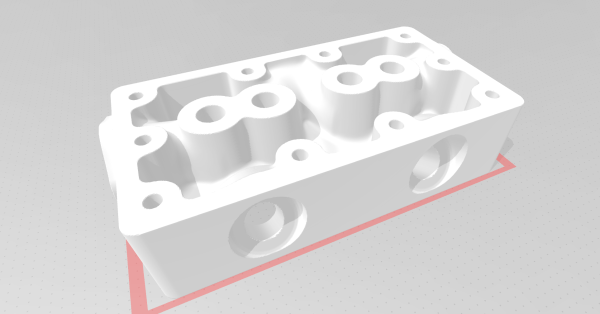
Once you have a shape, you can convert it to a solid. At that point, you can create a refined copy. This gives you a proper CAD file that you can export to a STEP file. From there, you can use it in FreeCAD or nearly any other CAD package you like to use.
Once you have a proper object, you can easily use it like any other solid body in your CAD program. This is one of those things you won’t need every day, but when you do need it, it’ll come in handy.
Want to up your FreeCAD game? We can help. There are other ways to hack up STL files. You can even import them into TinkerCAD to do simple things, but they still aren’t proper objects.
Continue reading “Reverse Engineering STL Files With FreeCAD”