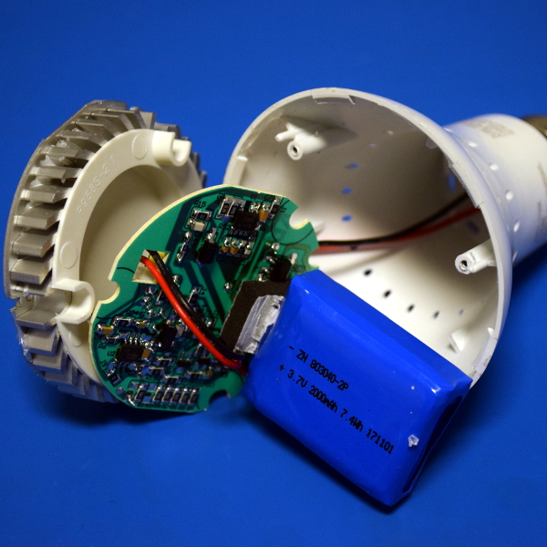
Recently I had the opportunity to do a teardown of a battery-backed LED bulb, and found some interesting details on how the device operated. Essentially, the bulb contained a low voltage DC uninterruptible power supply that would automatically switch between AC power and internal battery as needed. The implications of this seemed pretty exciting. For around $12 at big box retailers, this little bulb could be a cheap and convenient solution for providing fault tolerant power to microcontrollers and other low-power devices.
 The teardown was a runaway success, with quite a bit of discussion of the UPS idea specifically. Some people hated it, others loved it. But as we’ve come to expect from Hackaday readers, the comments from both sides of the aisle contained keen observations and invaluable real-world experience. From the safety of the device to the accuracy of the manufacturer’s claims, it seems like every element of the product was addressed.
I had ended the teardown with a promise that I’d continue experimenting with the tiny salvaged UPS, but even if I hadn’t, with so much feedback it seemed revisiting the subject was all but a necessity. It this little UPS really viable? Is it too dangerous to safely implement in your project? Will the thing just blow up?
So with your comments as a guide, and free of the somewhat restrictive teardown format, I set out to conduct a more thorough investigation of this little circuit that caused so much debate last month. It’s not all good news, but it’s not in the trash either. Not yet, anyway.
A Word on Safety (Or Lack Thereof)
Without a doubt, the most common complaint in the comments was that this device is not safe and shouldn’t be played with. Touching the traces on the PCB or one of the wires could give you a shock. Which of course is true, but that’s certainly never stopped a Hackaday reader before. Obviously it was never meant to be taken out of the bulb’s case, and as such it’s being used in a way that throws safety out the window.
Certainly the most obvious issue is the isolation, or more accurately, the fact there is no isolation. That’s right, the AC and DC sides of the board are connected. Now, if this was a USB charger or something along those lines, it would be a heinous design flaw. But remember, this is a light bulb. The user was never meant to see, much less touch, the internals. It’s hard to fault the designers for not worrying about isolation when the device in question was never meant to come out of its protective case.
But does the fact that the circuit isn’t isolated mean it can’t be safely used? Not necessarily. Just as the original bulb wasn’t dangerous since it was a sealed unit, if your design isn’t meant to be touched with by the user, there’s no immediate danger. Imagine something like an ESP8266 weather station that simply reads from sensors and sends its data out over Wi-Fi, such a device would likely live its life inside an enclosure anyway.
The real risk here is if you have some kind of project in mind where the user is expected to physically interact with it, or worse, plug something into it. Here the risk of electric shock is high enough that you’d want to steer clear. [Big Clive] examined a USB power supply with this problem awhile back, and illustrated the dangers:
Load Testing
So let’s say you’ve got a scenario where the lack of isolation won’t be a problem, perhaps the weather station example. How much current can this little device provide?
The run time for the LED light was given as 3.5 hours on the package, and since it had a 2,000 mAh battery, some back of the envelope math says that 400 mA is probably the best we can hope for. At least for an extended period of time, anyway. Testing this is easy enough, we just need to put an adjustable load on the DC side and start raising the current until the voltage dips.
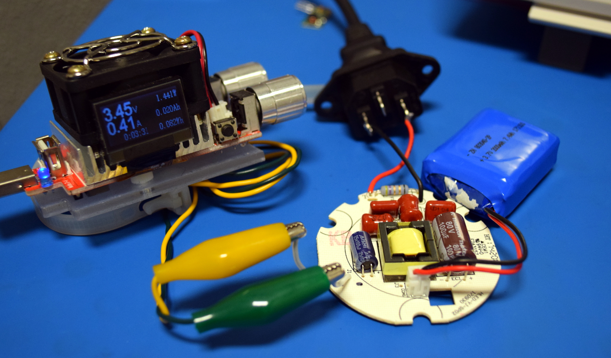
The estimated figure proves to be accurate, as the device can provide around 410 mA before the voltage starts dropping off. The maximum looks to be around 480 mA, so it’s a fairly narrow sweet spot.
Voltage Regulation
As a proof of concept in the teardown I soldered a Wemos D1 Mini to the DC side of the UPS board, and sure enough it powered up and worked fine. But it was also something of a risk. According to the load tester, the board is putting out nearly 3.5 V at the upper limits of its current capacity. When the current is lower, that voltage gets as high as 3.8 V. For sensitive 3.3 V devices, this could be an issue. Luckily the solution here is quite simple, just add a 3.3 V regulator.
You could also use boost converter to get up to 5 V, but with only 400 mA of current to play with on the input side, it’s not going to do much useful work.
The Real Problem: AC Mode
 Up to this point, I’ve only been dealing with the board when it was running on batteries. My hope was that when I switched on the AC, things would work the same and there’d be no issues. Sort of critical if this is to be used as an uninterruptible power supply. Unfortunately, that wasn’t to be.
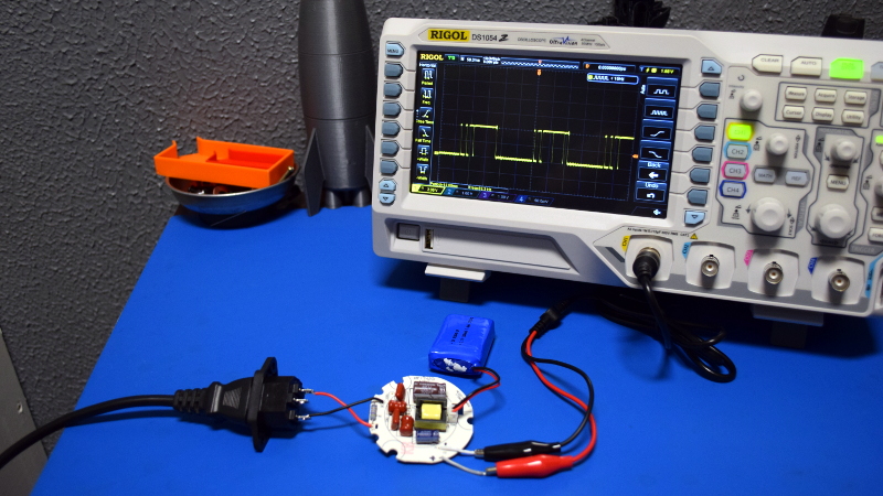
Once you connect AC power, the DC side starts pulsing along at (as you probably guessed) around 60 Hz. This is sort of a problem. It’s still outputting ~4 V DC, but it’s coming as a square wave; which worked fine for LEDs but certainly doesn’t play nice with microcontrollers and the like.
The solution here could potentially be a big enough capacitor to ride out the pulses. Perhaps use the output of the board to charge a super capacitor of a Farad or two.
Incidentally, hooking this non-isolated circuit up to your oscilloscope is a good a reason as any to either buy or build a stand-alone isolation transformer.
Accessories Sold Separately
After spending some more time experimenting with the board, I have to admit I’m considerably less excited then when I first pulled it out of the LED bulb. It seems there’s just no getting around the fact that you’ll still need to add additional hardware to get it truly working as a low-voltage UPS. My hope, which was inspired by the quick test with the ESP8266 during the teardown, was that this would be a turn-key solution for those looking to create AC powered devices with an integrated battery backup. But reality has a way of changing things up on you, unfortunately.
I still think it’s a very interesting board, and worth tracking down one of these battery backup LED bulbs just to experiment with it a bit. But unless you’re willing to start tacking additional components on it, its usability is severely hindered by the pulsed DC output when running on AC power.


Seems that a much easier/smarter plan would be to just wire your project to run off the battery directly. It wouldn’t turn off when the ‘light switch’ is off, but seeing as how it is an UPS I am pretty sure that is what you wanted anyway… Then you get compatibility with normal electronics looking for a single cell lithium input and probably a fair bit more current capacity if you wanted it.
Very good point, that is probably the better solution than trying to rectify the pulsed DC.
Would it not still put out very dirty DC if you hooked something up to that battery in parallel with the rest of the unit while it’s on AC power? I guess it would probably be alright, but I’d like to see that on the scope.
Deja Vu! https://hackaday.com/2018/04/23/teardown-led-bulb-yields-tiny-ups/
This is the follow up article. The one you linked was referred to in the very first sentence of this one.
Couldn’t be bothered to read the first line.
Why do we always get these type of comments? It’s like… wait fot it ……… Deja vue!
;-)
for those not familiar with the term, ‘déjà vu’ means “Something which one has or suspects to have seen or experienced before, especially when that is not the case.”
FWIW, I read about a study long ago, that proposed “deja vu” was caused by a slight delay between signals sent by an eye to the brain in relation to the other. What the first eye saw was processed and stored in the brain, and when the second (delayed) signal was processed, the brain (in effect) said, “I’ve seen that before.”
I’m not sure how elaborate you plan to go Tom, but I was just musing to myself how ‘smart’ a UPS light-bulb could be and to only come on in the case of a power cut rather than just turning the light-switch off.
All I could think of was trying some sort of back-powering of the live feed and effectively measuring the resistance of the live-neutral. If there’s a voltage difference then it’s probably switched off (“user requested darkness”) but if it’s effectively a short (as there’d be other items on the live trying to draw current) then it could be used a sign that the switch is on and so infer power must be out so turn on (at least for as long as battery will run for).
This bulb already does that. It measures the resistance between its two contacts. If it sees it is completely open circuit then it assumes somebody has turned it off at the wall switch.
I wish you had put a capacitor with a small load on the output when AC powered. And shown us if filtering was feasible.
Nothing I had seemed big enough to make much of a dent. Hence the suggestion of trying it with a supercap that had a few orders of magnitude more capacity.
Unfortunately, I don’t have any 5V supercaps on hand to test with, but doing some research it doesn’t seem to be a problem charging them with pulsed DC.
Oh!
Thanks!
If you put a 5v tolerant supercap (usually a pair of 2.5v supercaps in series) there to charge from the pulsed DC there are affordable and robust fully isolated DC/DCs available from the usual suspects (Delta, MuRata, etc.) that provide medical device grade isolation up to several kV and gracefully tolerate a mains frequency common mode thrash such as you get from having your input coming off a transformerless power supply like this).
That said, those supercaps ring in around a buck a piece and the DC/DCs I had in mind cost about 8 bucks (all qty. 1) so it would sort of negate the win on the cheap bulb to microcontroller UPS front but then you could make a device that would be able to have wired communications with the outside world and be touched by users (so long as you kept the input side before the DC/DC enclosed properly).
Oh well. I guess this is not what I was looking for then. What I need is a really short lived UPS for a RasPi. I don’t feel that my engineering skills are up to this task yet but I’m working on it.
I know that there are RasPi UPSs available for sale on the net. They are overkill for my needs though. They are meant to keep the Pi going through the outage. That’s overkill for me as I do not want that. I want to use the PI’s GPIO to sense when power goes out and initiate a proper shutdown. I only need the UPS to last until the end of the shutdown. Everything else is just unnecessary expense.
Why?
To make RasPi appliances. My first thought being Octoprint. I want to power my Pi from my printer’s power supply. When I turn the printer off I want the Pi to turn off too but I want it to be a proper shutdown. I am imagining being able to turn off my printer’s main power switch (or not), unplug the printer, pick it up and carry it away with no more thought than moving a vacuum cleaner from one wall outlet to another. The pi should stay alive long enough to unmount it’s filesystems properly. That is all.
Any ideas?
The pi of course should boot back up when power is reapplied (which Pis do naturally).
Read only filesystem…
Sure, but then you have a read only filesystem!
For some projects that might be fine. For others maybe not. In the case of an Octoprint server that would mean no uploading stls into the Pi’s storage. No adding or removing plugins. No updates.
Of course you can switch the filesystem temporarily into R/W mode and put it back when you are done. That kills the ‘it’s just an appliance’ illusion though.
Mount a USB drive as a read write partition and you’re there. I do this exact thing with commercial hardware that contains a raspberry pi with a read only filesystem. ;)
The readonly filesystem is a good idea, but if you really want to do a proper shutdown, you could potentially use an Adafruit Powerboost 1000C (basically a pass-through USB battery pack: it provides 5V out and seamlessly switches between USB / LiPo power as available) to provide you a bit of power when your mains power goes out. Then you could use a SleepyPi to read from the PowerBoost to sense that mains power is gone and initiate a Pi shutdown. Kind of complicated, but it seems doable.
I was imagining that since the Pi only had to run for a minute or two on battery that something would be possible that was significantly smaller and cheaper than a solution meant to run for a time. I was picturing maybe even something that ran off of a rechargable AA cell. The 1000C doesn’t look to bad though. Maybe I will go with that, thanks.
The sleepy pi does look like overkill though. I was imagining just taking the DC input (pre UPS), running it through a voltage divider to get 3.3V and connecting it to one of the GPIOS. Then I would set an interrupt to start a shutdown timer if the pin goes low, kill the timer if it goes high again. (if you can do that on the Pi, I haven’t played with Pi GPIOS yet)
If interrups aren’t an option checking it via a 1-minute cron job would be ok too.
If you want to cost cut then this is a great alternative to the Adafruit Powerboost.
https://www.banggood.com/37V-Liion-Battery-Mini-USB-To-USB-A-Power-Apply-Module-p-928948.html?p=9B1915347037201311DI&cur_warehouse=CN
You will get charging and pass-through at the same time. and Under/Over charge protection
You do miss some of the features the Adafruit provides. Such as built in on/off function & battery level status via Pin & LEDs.
You could go even simpler with a 5v DPDT relay. Wire a 5v input to the relay coil, one side of the DPDT relay and input of lipo charger/boost converter. Wire the output of the lipo charger/boost converter to the other side of the DPDT relay. Wire up your device and a large enough bulk capacitor to the switching contacts of the DPDT relay. Presto a UPS.
When there is power available the DPDT relay will be energized running your load off the available 5v power and charging the lipo. When the power fails the DPDT relay will be deenergized switching your load to the output of the lipo boost converter and running it off battery till the lipo fails or power returns. The large bulk capacitor will take care of the momentary milliseconds loss of power as the relay switches from one source to the other.
This is essentially how basic mains computer UPSes work, just replace the DC boost converter with a 120vac inverter and remove the bulk cap. Most AC loads will barely hickup at the relay switching transition. cause you’re mostly talking about resistive loads like light bulbs, motor loads which can just idle though the switching transition or loads like switchmode/linear power supplies that have capacitors in them already to ride out the switching transition.
The home page photo shows an adjustable load connected to something. I read the piece to find out more and there is no mention or photo? Did I miss something?
How is that possible? It’s dead center in the post, the biggest image on the page.
here is the photo..
https://hackaday.com/wp-content/uploads/2018/05/upstest_load.jpg
the yellow+dark_green wires appear to come from nowhere, the load tester’s USB plug is not plugged into anything. that is where the confusion comes from. (the load tester is connected to the bulb’s UPS pcb; it’s just not easily apparent to everyone.)
It’s only confusing if you try to make it so. That whole part of the post is about load testing the PCB. You see a PCB, you see a load tester, and yet you aren’t sure if they are connected? Come on.
It’s not a magic trick, the yellow/green wires must be connected up to the back somewhere.
Tom, that 60hz ish waveform almost looks like a switch mode in discontinuous mode with no load and no output capacitance.
The very first pic in the article appears to be the CRO connected direct to the output with no load.
Does the waveform change with a varying load?
I would have imagined a cap of only 1000uf (or even less )would have made a significant change to the waveform.
If you want a UPS for your microcontroller, note that a LiFePO4 can be float-charged on a 3.3-3.6V regulator. These cells are readily available in handy sizes like CR2, CR123,14500 (AA), etc, which will run a micro for days or months depending. The same principle scales up to much larger cells if you want to power lights etc.
If your micro isn’t 3.6V-tolerant, then charging up to only 3.3V is OK and you’ll just be forgoing some of the battery capacity.
Get a cheap+safe 5V input (USB charger, solar, whatever), regulator, diode (if your LDO conducts in reverse) and LiFePO4 then connect that to your “3.3V” micro, which you have carefully selected to be tolerant of 2.7-3.5V or whatever covers your chosen charge range for the LiFePO4 cell.
You can monitor the cell voltage with an ADC and shutdown/disconnect when the battery is close to depletion.
There are special chips that cost next to nothing that do this. I wouldnt trust the pi doing this safety feature.
Search ebay for dw01
You can buy those cylindrical powerbanks on eBay for 1 dollar, they have circuit for charging LiIon to 4.2V from 5V input, protection circuit to prevent overdischarge of a cell and integrated 3-4.2V to 5V step-up converter with 1A output. They’re quite usable even for very small currents (unlike most powerbanks that will switch off if load is less than 100s of milliamps). Source some discarded laptop battery and you have UPS that will keep uC running for months, all for a dollar or two.
FWIW, here’s an example of disabling load detection on a larger powerbank PCB:
http://arduino-geiger-pcb.blogspot.com/2017/03/cheap-but-all-inclusive-solution-how-to.html