Many readers will be familiar with interfacing I2C peripherals. A serial line joins a string of individual I2C devices, and each of the devices has its own address on that line. In most cases when connecting a single device or multiple different ones there is no problem in ensuring that they have different addresses.
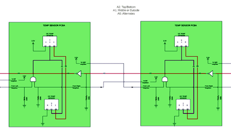
What happens though when multiple identical devices share an I2C bus? This was the problem facing [Sam Evans] at Mindtribe, and his solution is both elegant and simple. The temperature sensors he was using across multiple identical boards have three pins upon which can be set a binary address, and his challenge was to differentiate between them without the manufacturing overhead of a set of DIP switches, jumpers, or individual pull-up resistors. Through a clever combination of sense lines between the boards he was able to create a system in which the address would be set depending upon whether the board had a neighbour on one side, the other, or both. A particularly clever hack allows two side-by-side boards that have two neighbours to alternate their least significant bit, allowing four identical boards each with two sensors to be daisy-chained for a total of eight sensors with automatic address allocation.
We aren’t told what the product was in this case, however it’s irrelevant. This is a hardware hack in its purest sense, one of those which readers will take note of and remember when it is their turn to deal with a well-populated I2C bus. Of course, if this method doesn’t appeal, you can always try an LTC4316.


All is fun and games until one of them breaks or gets a bad connection — good luck debugging then.
Just use a 4-bit binary adder like a 16-pin package 74HC283 plus 1 decoupling cap for Vcc, connect the required number of A inputs to outputs from previous neighbor with weak pull up/down resistors or array, all B inputs to 0, Cin to 1, discard Cout and route all required outputs to next neighbor. Each 74HC283 is then a +1 adder.
This way, you get up to 16 automatic device addresses with the addition of log2(n) required daisy-chain connections between devices.
Would you detail this circuit or provide it ? It searched for “I2C 74HC283” without results.
I can try to explain. the 74HC283 is an adder. Normally it adds the 2 inputs (A&B) together and If you turn Cin on it will count +1 onto the result. By connecting the ouput of one adder to the input (A) of another, Leaving the other input (B) connected to the ground and Cin to VCC you get that the output of each adder will be the output of the adder before it +1.
So you get that:
Adder 1 will output 0001 to adder 2
Adder 2 will output 0010 to adder 3
Adder 3 will output 0011 to adder 4
and so on.
By connecting the outputs of each adder to an I2C device’s address pins you would get an automatic address for every Adder+I2C device you add to the chain.
Exactly!
Unfortunately, it is not possible to post a picture here.
Here you go:
https://wordpress.com/post/squonk42.wordpress.com/176
https://squonk42.wordpress.com/2018/05/23/i2c-daisy-chained-address-generator/ <– would be the correct URL wouldn't it?
Hi nino, It is probably best to initially search for “74HC283 datasheet” and take it from there. The description above along with the pin-out should take you toward the solution. :) Looking for an I2C related search might be too specific.
BTW, if the device is an MCU, this solution basically comes up for free.
The concept is interesting, but I would have chosen an SPI devices. I know the offer is a lot smaller, but that is a tried and tested solution.
Seems like a classic application for ‘1-wire’ temperature sensors which have global addresses and a ‘count off’ functionality built into the protocol to identify all of the sensors on a network. Doesn’t tell you physically where each sensor is though ;-)
That sure is applying the KISS principle… downside is it needs a few more signals to work.
https://hackaday.io/project/24932-toy-synthesizer/log/60250-peripheral-detection-and-ic-bus-enumeration was my attempt, haven’t tried writing the code for that yet.
The AND gate selects the 2 inner nodes. One could use a NAND gate instead to select the two outer nodes. By doing so, a single 2-gate 2-input NAND chip (eg. NL27WZ00USG in a US8 pkg, $0.30ea in 10+ quantities) would suffice: one gate goes high on the outer nodes, and the other gate with the inputs tied becomes an inverter.
A binary adder would cost nearly double, and the TCS9548A about 4 times, as would a µC. In high volume production, shaving pennies off the cost quickly becomes huge.
This is simple, cheap, and robust; just the kind of hack I like. Kudos, Sam!
A binary adder costs double, but provides up to 16 node addresses
If board space isn’t an issue, the quad NAND gates (74LVC00) are 2 cents cheaper (in 10s). They also leave you with an extra pair of gates for another function if it’s needed.
+1
True. The one I checked was about the same price, but I didn’t search exhaustively. The benefit of amortized R&D, I suppose.
This is pretty nice, I might use it some day. When I read the title I thought of some kind of automatic enumeriation where the devices are MCUs. Has anyone done that?
It reminds me of the I2C HUB I did some time ago for the joystick port of MSX computers
http://hotbit.blogspot.com.br/2007/07/hb1240-hub-i2c.html
http://1.bp.blogspot.com/_fI5GYCoy1yM/Rnni4aFM69I/AAAAAAAAAVg/39jPZYtVgMM/s1600/picoHUB.jpg
You could use a WIRED-AND gate instead using only diodes which would make that much cheaper than a CMOS chip. And then instead of a inverter, use a single FET with a pull-up resistor which again would be much cheaper than a CMOS chip. Even if you consolidated the two using NAND gates instead, the wired logic using diodes and a single transistor would be MUCH cheaper.
Diodes and FETs probably wouldn’t be cheaper than a NAND gate here. 74LVC00 is a quad NAND for 0.28 in 10s from digikey. Diodes are 0.10 minimum for a dual package or 0.09 for a single. Fets about the same. Also if power is an issue, the LVC part is much lower power than RTL or Diode logic when idle.
I agree, the 74LVC00 solution is the cheapest for 4 addresses (2 devices per board), and the 74HC283 solution is good if you need to expand to 16 addreses. The NL27WZ00USG otoh is the smallest footprint, thank you everyone!
Here is yet another idea how to solve it
https://github.com/gkasprow/Sensor-Box/issues/11