Here at Hackaday, we’re suckers for vintage instruments. More than one of our staffers has a bench adorned with devices spanning many decades, and there’s nothing more we like reading about that excursions into the more interesting or unusual examples. So when a Tweet comes our way talking about a very special oscilloscope, of course we have to take a look! The Tektronix 519 from 1962 has a 1GHz bandwidth, and [Timothy Koeth] has two of them in his collection. His description may be a year or two old, but this is the kind of device for which the up-to-the-minute doesn’t matter.
A modern 1GHz oscilloscope is hardly cheap, but is substantially a higher-speed version of the run-of-the-mill ‘scope you probably have on your bench. Its 1962 equivalent comes from a time when GHz broadband amplifiers for an oscilloscope input were the stuff of science fiction. The 519 takes the novel approach of eschewing amplification or signal conditioning and taking the input directly to the CRT deflection plates. It thus has a highly unusual 125Ω input impedance, and its feed passes through a coiled coaxial delay line to give the trigger circuits time to do their job before going into the CRT and then emerging from it for termination. It thus has a fixed deflection in volts per centimeter rather than millivolts, and each instrument has the calibration of its CRT embossed upon its bezel.
The 519 would not have been a cheap instrument in 1962, and it is no accident that there are reports of many of them coming back to Tek for service with radioactive contamination from their use in Government projects. We can’t help wondering whether the Russian equivalent super-high-speed ‘scope used the same approach, though we suspect we’ll never know.
If vintage Tek is your thing, have a look at their PCB manufacture from the 1960s.
Thanks [Luke Weston] for the tip.


There are grammar teachers doing 10000 RPM in their graves because of titles like this. Try “An Oscilloscope For The Nuclear Age”
To be fair, it’s a good way of starting a nuclear war.
Quick, let’s hook a generator shaft up to the corpses and build a necrophiliac electric generator!
You got the “necro” right but the “philiac” is very disturbing.
I was trying to think of the right term… but yes, the mechanical linkage would be quite disturbing.
Necrolectric generator
inb4 necromongers
https://www.youtube.com/watch?v=Z8yW5cyXXRc
Thanks!
I loved it!
I think my original was “A ‘scope for the nuclear age”. I’ll dive in and edit my editor. :)
Depends on how you hook them up to the drive shaft.
We used 519 scopes in the early 80’s. They were being replaced by the 7912’s. It was a digital scope that could capture 512 points with a total duration of 5 ns up to 9 bits. 500 MHz band width.
My father worked at Tektronix back then (and until he retired in ’96) He told me about some nuclear tests where they had a ‘scope (or maybe several) hooked up to sensors at the test site. They’d have a camera aimed at the screen and when the bomb went off, the information was sent back to be recorded at a safe distance. The ‘scope(s) were, of course, vaporized in the process. When I was a kid, that was interesting, but now I wonder how they got the image transmitted when they had, at best, microseconds. I’d ask him now, but sadly, he died a little over a year ago.
I have no idea if this is related to your late father, but:
In the late ’60s I was doing electronic design in Santa Barbara, CA. The local Tek rep was a really nice guy, and one reason was that from time to time he’d come by with a bag of Tek probes to give away. All of us who were hams had cheap ‘scopes with Tek probes. The reason he had them was because EG&G also had an operation there, and they needed a lot of high-end scopes (for one-time use), but had no need for the probes.
Any chance your name is “Cook”?
If, per chance, you meet that Tek rep after the atomic apocalypse, he’ll be more than happy to accompany you to Sanctuary Hills.
Nope, Buchanan. My father worked mostly in Chicago, Indianapolis, Atlanta, and Orlando. He was a sales manager in Chicago (or something like that, I was maybe 7 at the time.), he voluntarily demoted himself back to electronic tech. He mostly worked on medical equipment (Tek made medical electronics in the ’60s, they, but then, as my father said, “Every time someone dies in a hospital, the manufacturers of every piece of equipment in the room are named in the lawsuits.”), ‘scopes, and television equipment. The last year he worked for Tek, he worked a *lot* of hours at the Atlanta Olympics, maintaining the video equipment for the events.
We still have our Santa Barbara Special Technologies Laboratory office. ;)
What an interesting story! And thanks. I never cease to be amazed by the breadth of experiences within our community.
If the cameras captured at the common 24fps, you’d need at least two frames to be sure you got the trace from the scope, assuming the camera and oscilloscope aren’t synchronized.That’s just over 80ms, so if they actually had microseconds, that would never work.
It’s also very inefficient, data-wise; the video feed contains a whole lot more information, and would therefore need more bandwidth, than the signal being measured by the scope. The trick is they, apparently, only needed a single trace of the scope, and with the technology available at the time, this was probably the easiest way to stretch time from the nanosecond scale on the scope to something that could be transported across many kilometers, all using commercial off-the-shelf equipment.
Consider doing something similar now, but with the frequency a few orders of magnitude higher; say 1THz bandwidth, and you’re trying to capture a single event, so you can’t do any undersampling tricks that require repetitive waveforms. How would you go about it?
I wish he were alive to ask. I know they had a virtually unlimited budget and access to the manufacturers of best test equipment made, including Tektronix, of course. My gut feeling is that they synchronized the camera to the sweep of the ‘cope (one-shot triggering). They might have used a medium persistence phosphor, and maybe more than one camera, with optical splitting of the trace, part to each camera. Or maybe not, I’ll have to think whether that would work. Surely *not* 24 frames/s, but something much faster. I wonder if turning the raster on its side and scanning up and down over only the area that the trace was supposed to be would speed it up? Somehow they had a method.
Someone mentioned below that they used film cameras with other brands of ‘scopes and sent someone in to pick up the film afterward. Obviously, it would have to further from the actual bomb that I was assuming…
John W. Campbell (yes, the SF writer and editor of Astounding) wrote an article in CQ magazine in the late fifties about wide bandwidth scopes. He’d visited Bell Labs and they were doing scopes without amplifiers. It was something like lower the anode voltage, which made it more sensitive, but kind of a tiny deflection. It’s been a while since I read the article. But something happened that was more than just doing away with amplification. He mentioned a magnifying glass, and something about Bell Labs making CRTs specifically for the purpose.
Michael
Interesting! I wonder if they could make the tubes longer to increase the sensitivity, since the same angular deflection would cause a larger linear deflection, or would that require increasing the anode voltage to get sufficient acceleration, negating the effect?
Alternatively, you might consider tilting the front of the screen, but that would probably completely ruin the focus.
A magnifying glass or similar lens might work, but it would require a very tight beam (small spot) to be useful; a deflection on the order of magnitude of the spot size is hardly usable.
I worked for EG&G in the late 60s and 70s. They had 1 GHz cathode ray tubes in oscilloscopes for use at the Nevada Test Site. Philips around that time had developed a 5 GHz CRT for use by the French equivalent of the AEC. Such ‘scopes were fitted with film cameras located some distance from underground “detonations” and, unless there was a danger of ground collapse or radiation leakage, teams were sent in to recover the film.
I wonder if they did the same with the Tek ‘scopes, that would solve a lot of technical
problems discussed above.
The ‘scopes also used the Rossi technique for displaying a time-dependent signal (in this case, a rapidly rising positive exponential). Some details can be found here: http://kmh-lanl.hansonhub.com/publications/maxent00.pdf
I am at the Las Vegas operations and have actually recently been playing with our old Rossi Scopes and comparing dynamic range between them and some of the newest tektronix digitizers. Man, are there a lot of steps and external devices to get these Scopes to run!
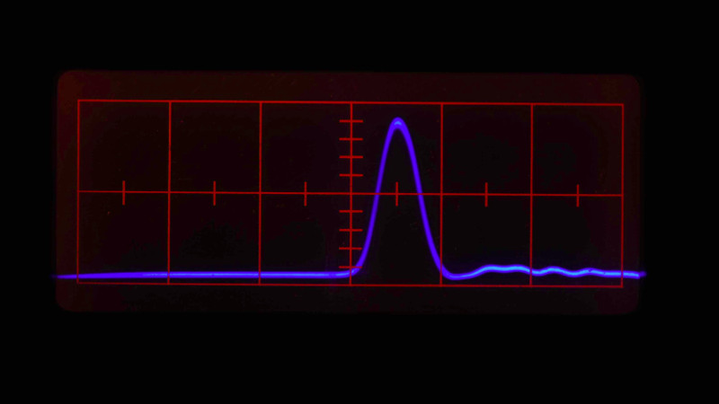
I have a working 519 as well. It huge, heavy, loud, and amazing. The horizontal amplifier section uses an RF transmitter tube. I’ve never seen a trace so sharp and blue. My adventures in reforming all of the caps and subsequent power-up can be found here: https://paulcarbone.com/blog/tektronix-519-other-ramblings/
A great read, thanks for the link!
I used a 519 in the ’70s in a test of voltage breakdown of 709 op amps. I used a B&W Polaroid scope camera and cranked the brightness on the scope to max. I used up a lot of film, and a lot of 709s.