The 555 timer IC is a handful of active components all baked into one beautifully useful 8 pin package. Originally designed for timing purposes, they became ubiquitous parts that can achieve almost anything. In this case, they’re being used to create a basic PWM motor controller.
The trick is to set the 555 up in astable mode, and use diodes and a potentiometer in the charge/discharge loop. By hanging a diode off either side of a potentiometer, leading to the charge and discharge pins, and connecting the center lug to the main capacitor, you can vary the resistance seen by the capacitor during charge and discharge. By making charging take longer, you increase the pulse width, and by making discharge take longer, you reduce the pulse width. The actual frequency itself is determined largely by the capacitor and total resistance of the potentiometer itself.
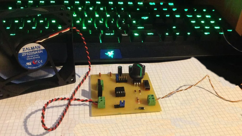
This is a very old-school way to generate a PWM signal, which could be used to vary intensity of a light or make noise on a buzzer. However, in this case, the output of the 555 is connected to a MOSFET which is used to vary the speed of a computer fan motor.
It’s an excellent way to learn about both PWM motor control and the use of 555 timers, all with a very low parts cost and readily available components. We’ve seen such setups before, used as easy-to-build dimmer switches, too.


A similar PWM generator made with 2 gates of 74HC04, 2 diodes, 1 capacitor, 1 trimmer :
https://cdn.hackaday.io/images/4174071470535140513.png
(see https://hackaday.io/project/8693-dypled )
Needs a Rpi to be complete though
Wait, where’s the Arduino?
I remember many years ago using 2 555’s to generate a pwm signal to drive a big arse valve for an induction heater many years ago as an emergency replacement for a big computer controlled system. The client was most impressed that his Big machine could keep running.
When the cement around the rheostat controlling the heater fan speed of my car crumbled and set my cardboard ducting on fire, I replaced it with the PWM controller of a fairly recent 14V cordless drill. Heart of the circuit was a NE555 so guess what, the 555 still holds up as a financially viable choice in “as cheap and reliable” as production allows.
I could’ve done that with a 555!
Oh, wait…
The 555 + diode trick to expand the PWM range was the same circuit I found in my Milwaukee cordless drill when it finally wore out and I gutted it.
I built a similar circuit years ago for my father-in-law. It had two potentiometers to adjust the on and off time to control a solenoid that simply pressed a key on a keyboard. He was converting databases for trash company software; and some of them would only go to the next screen with a key press. He would capture the screen (it was all text) and press the key. It worked great.
Wonder if this could be scaled to replace the pre ’88 Club Car golf cart toaster oven speed control system? The current system uses a series of 5 solenoids that are switched to enable or bypass 3 resistor coils to vary the speed of the cart. The resistor coils and solenoids get warm and the solenoids are prone to failure.
Ugh. Another instructables link. I hate that site. Plastered with ads, posts broken up into multiple parts to generate clicks… Now the only click it generates from me is “close”.
What Ads ?
Indeed :)
It’s still an awful site encouraging us to lock up our knowledge for want of a bit of web hosting for some text and images.
So I was wondering why 555 timers are as expensive as microcontrollers (if not more so). Mirocontrollers can do nearly everything the 555 can and so much more. Someone told me it’s due to the packaging cost becoming more significant at lower prices. Can anyone tell me if this is true or explain why?
Anyways, these builds using obsolete parts are cool. I like the vacuum tubes and core memory because they look so steampunk.
I don’t think it’s packaging costs. There are 555s that come in SOT-23-5 and they’re more expensive than the ones in SO8. I think it has to do with the 555 being an analog part that operates over a wide range of voltages and has an output state that sinks or sources up to 200mA of current, which probably limits how small they can get the die.
I hate this instructables link because apparently it uses some magical web tech that Chrome browser on Linux doesn’t understand, so none of the buttons work, like “download PDF”. It would be nice if the schematic were just ON THE PAGE, instead of behind some Javascript crap. You kids get off my lawn!
Fan itself has a speed controller build-in to control two-phase BLDC motor. Some fans can be modded by adding potentiometer.
I’d be interested in that hack. The spec says 25 kHz 5V PWM: http://www.formfactors.org/developer/specs/REV1_2_Public.pdf
I meant ripping into the fan itself. You will need one sacrificial fan to learn pcb layout and IC used.
I had a free box of 20 Nidec server fans, 130CFM = unusable near humans. Dropping input voltage would slow them down, but also weaken to the point of not starting when set to very low rpm.
Googled used IC and found its fixed speed(no external pwm control), but the speed itself was dependent on RC circuit = win.
I was looking for overspeed controlled by 555 timers, just removing fan speed control ic, and use only coils… In this case just use pc software for 4th fans to control, or change capacitor inside fan (3-2pins not regulated just as IC inside lets). For 4pin better use arduino and take temp and adjust speed off to max fan speed if need (only 4pin fan’s). Good luck.