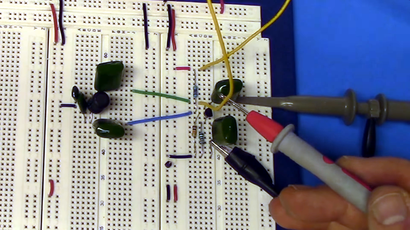
The Colpitts oscillator is a time-tested design — from 1918. [The Offset Volt] has a few videos covering the design of these circuits including an op-amp and a transistor version. You can find the videos below.
You can tell a Colpitts oscillator by the two capacitors in the feedback circuit. The capacitors form an effective capacitance for the circuit (assuming you have C1 and C2) of the product of C1 and C2 divided by the sum of the two capacitors. The effective capacitance and the inductance form a bandpass filter that is very sharp at the frequency of interest, allowing the amplifier to build up oscillations at that frequency.
It is unusual to show an op-amp oscillator, and it is interesting to think about the design changes and limitations discussed in the video. The video isn’t just theoretical. He also builds the circuit and looks at the real world performance.
It is also interesting to look at the difference between the op amp and the bipolar circuit. Of course, you can use other active devices like a FET, too. This is also an important circuit when a crystal is part of the feedback circuit instead of an inductor.
We see a lot of these as low-power ham radio transmitters. If you want to see a different oscillator design, we talked about Pierce oscillators before.


Handy hint, at TAFE we learned to remember the difference between Hartley and Colpitts oscillators with [H]artley being tapped [H]enries (inductance) and [C]olpitts was tapped [C]apacitance.
My professor in college that taught this part of circuit design was very practical, everything was open book. In some ways, that was easy. But on the final exam, he would give us the circuit, like this or other oscillator types, because they were often a recipe, so the question was an essay, given this circuit, and it isn’t oscillating, what do you do?
Easy if you really understand what’s going on.
The answer is simple but tricky, it was designed to oscillate, therefore, it won’t!
Design an amplifier if you want an oscillator!
B^)
Last time I tried to build an amplifier the result was a radio would pick up only Disney channel kids music or Rush Limbaugh’s conservative talk show.
This type of oscillator is widely used in inductive loop vehicle detectors. I used them in my design too: https://hackaday.com/2017/11/04/inductive-loop-vehicle-detector-gets-modernized/
This video is a better education than at school. Thanks for all the details
more like this!
I know this is a subject where even the references disagree wildly, but I’d call the circuit shown above a Pierce oscillator. That’s the one where the node between the capacitors connects to GND.
The Colpitts topology grounds the node where C1 and L1 meet in the circuit diagrams shown above:
https://en.wikipedia.org/wiki/Colpitts_oscillator
As I understand them, the Pierce topology is a high quality phase-shift oscillator. Both capacitors act as delay elements in low-pass filter stages: R1-C1 first-order, L1-C2 second-order (I’m afraid the statement that L1-C2 form a high-pass filter isn’t correct.. DC current can flow around the R1-L1-RI-RF feedback path, and high-pass filters block DC). The two low-pass filter stages provide about 180 degrees of phase shift. The inverting amplifier provides enough phase shift to take the total around the loop to 360 degrees, and provides enough gain to cancel the attenuation through the two low-pass stages.
What I call a Colpitts oscillator behaves more like a relaxation oscillator with a frequency-sensitive switch. The amplified output goes to the node where the two capacitors meet, the upper capacitor acts as a positive feedback element, and the inductor is a shunt to GND. With those connections, the capacitor and inductor do form a high-pass filter from the output back to the amp’s positive input. The lower/grounded capacitor forms a low-pass filter with the amplifier’s output resistance, and the overall feedback path is a band-pass filter like the description in the videos above.
My mental rule of thumb: if the inductor/crystal is in series with the feedback signal (feedback flows through it and back to the amplifier’s input), it’s a Pierce oscillator. If the inductor/crystal is a shunt for the feedback signal (it diverts energy away from the amp’s input and sends it to GND), it’s a Colpitts.
I’ll give careful consideration to any reasoned argument that the circuit above should be called a Colpitts though. Like I said, I’ve seen different references give each topology every possible name, so I’m far from convinced my answer is the right one.
I loved this tutorial.
I’m currently designing metal detector circuits (including magnetic detector, LC tank circuit, and pulsed induction difference-coil eddy-current detection circuits) for use as demonstration pieces in our physics lab, and this tutorial was incredibly useful for figuring out how to set up an OP-AMP version of the Colpitts oscillator (and understand what I was doing).
Hi
Very very goooood