Crystal Oscillators Explained

We’ve read a lot about oscillators, but crystal oscillators seem to be a bit of a mystery. Hobby-level books tend to say, build a circuit like this and then mess with it until it oscillates. Engineering texts tend to go on about loop gains but aren’t very clear about practice. A [circuit digest] post that continues a series on oscillators has a good, practical treatment of the subject.

Crystals are made to have a natural resonant frequency and will oscillate at that frequency or a multiple thereof with the proper excitation. The trick, of course, is finding the proper excitation.

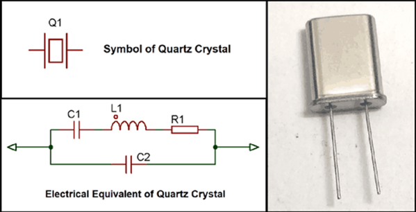
The post starts with a basic model of a crystal having a series capacitance and inductance along with a resistance. There’s also a shunt or parallel capacitor. When you order a crystal, you specify if you want the resonant frequency in series or parallel mode — that is, which of the capacitors in the model you want to resonate with the inductor — so the model has actual practical application.
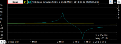
By applying the usual formula for resonance on the model you’ll see there is a null and a peak which corresponds to the two resonance points. The dip is the series frequency and the peak is the parallel. You can actually see a trace for a real crystal in a recent post we did on the Analog Discovery 2. It matches the math pretty well, as you can see on the right.

Continue reading “Crystal Oscillators Explained”

A Radar Module Teardown And Measuring Fan Speed The Hard Way

If you have even the slightest interest in microwave electronics and radar, you’re in for a treat. The Signal Path is back with another video, and this one covers the internals of a simple 24-GHz radar module along with some experiments that we found fascinating.

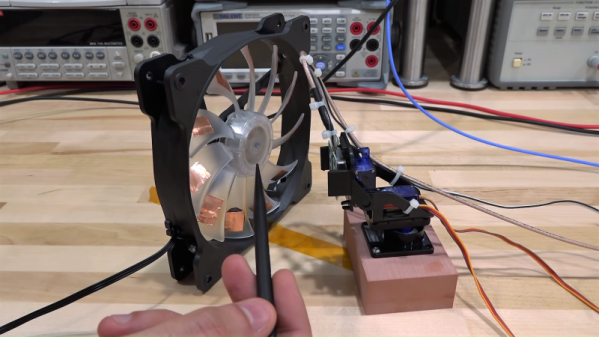
The radar module that [Shahriar] works with in the video below is a CDM324 that can be picked up for a couple of bucks from the usual sources. As such it contains a lot of lessons in value engineering and designing to a price point, and the teardown reveals that it contains but a single active device. [Shahriar] walks us through the layout of the circuit, pointing out such fascinating bits as capacitors with no dielectric, butterfly stubs acting as bias tees, and a rat-race coupler that’s used as a mixer. The flip side of the PCB has two arrays of beam-forming patch antennas, one for transmit and one for receive. After a few simple tests to show that the center frequency of the module is highly variable, he does a neat test using gimbals made of servos to sweep the signal across azimuth and elevation while pointing at a receiving horn antenna. This shows the asymmetrical nature of the beam-forming array. He finishes up by measuring the speed of a computer fan using the module, which has some interesting possibilities in data security as well as a few practical applications.

Even though [Shahriar]’s video tend to the longish side, he makes every second count by packing in a lot of material. He also makes complex topics very approachable, like what’s inside a million-dollar oscilloscope or diagnosing a wonky 14-GHz spectrum analyzer.

Continue reading “A Radar Module Teardown And Measuring Fan Speed The Hard Way”

A Graph Plotting Metal Detector

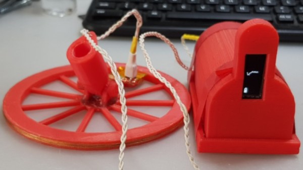
Metal detectors can be a great source of fun, and occasionally even found wealth. They allow the detection of metal objects at a distance, enabling hidden treasures to be discovered. They’re also highly critical to the work of minesweepers and unexploded ordnance disposal teams. [Andrius] wanted to add such a device to his kit when motorcycling through the woods of Lithuania, and thus decided to undertake a build of his own. (Editor’s note: original link went bad, this is through the Wayback Machine.)

The detector is a thoroughly modern one – fans of the 555 may want to look away now. A Collpits oscillator, built from two transistors, is used to generate a frequency that is passed through the detection coil. This frequency is measured by an Arduino that plots a graph of the received frequency on an OLED display. As the coil is passed near metal objects, the oscillator frequency changes, and this is visible on the frequency plot on-screen.

Not only is it a quick and easy build that is achievable from what are now junkdraw components, it’s also one that would be readily usable by the hearing-impaired, too. It’s a great project to tackle if you’re looking to get to grips with basic oscillators, frequency measurement, or just microcontroller programming in general.

Still need more inspiration? We’ve seen a similar concept executed before.

The Colpitts Oscillator Explained

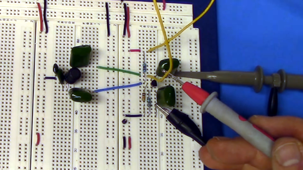
The Colpitts oscillator is a time-tested design — from 1918. [The Offset Volt] has a few videos covering the design of these circuits including an op-amp and a transistor version. You can find the videos below.

You can tell a Colpitts oscillator by the two capacitors in the feedback circuit. The capacitors form an effective capacitance for the circuit (assuming you have C1 and C2) of the product of C1 and C2 divided by the sum of the two capacitors. The effective capacitance and the inductance form a bandpass filter that is very sharp at the frequency of interest, allowing the amplifier to build up oscillations at that frequency.

Continue reading “The Colpitts Oscillator Explained”