Crystal Oscillators Explained

We’ve read a lot about oscillators, but crystal oscillators seem to be a bit of a mystery. Hobby-level books tend to say, build a circuit like this and then mess with it until it oscillates. Engineering texts tend to go on about loop gains but aren’t very clear about practice. A [circuit digest] post that continues a series on oscillators has a good, practical treatment of the subject.

Crystals are made to have a natural resonant frequency and will oscillate at that frequency or a multiple thereof with the proper excitation. The trick, of course, is finding the proper excitation.

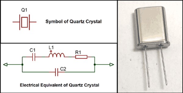
The post starts with a basic model of a crystal having a series capacitance and inductance along with a resistance. There’s also a shunt or parallel capacitor. When you order a crystal, you specify if you want the resonant frequency in series or parallel mode — that is, which of the capacitors in the model you want to resonate with the inductor — so the model has actual practical application.

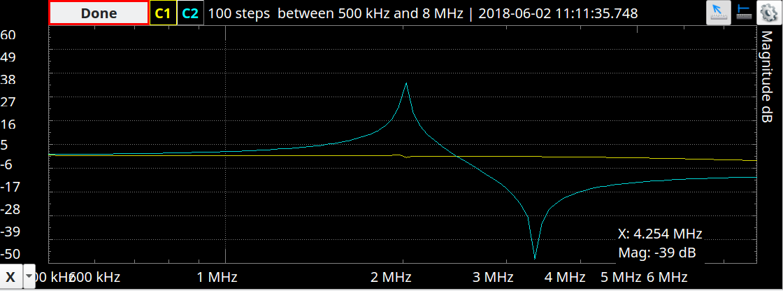
By applying the usual formula for resonance on the model you’ll see there is a null and a peak which corresponds to the two resonance points. The dip is the series frequency and the peak is the parallel. You can actually see a trace for a real crystal in a recent post we did on the Analog Discovery 2. It matches the math pretty well, as you can see on the right.

Continue reading “Crystal Oscillators Explained”

The Colpitts Oscillator Explained

The Colpitts oscillator is a time-tested design — from 1918. [The Offset Volt] has a few videos covering the design of these circuits including an op-amp and a transistor version. You can find the videos below.

You can tell a Colpitts oscillator by the two capacitors in the feedback circuit. The capacitors form an effective capacitance for the circuit (assuming you have C1 and C2) of the product of C1 and C2 divided by the sum of the two capacitors. The effective capacitance and the inductance form a bandpass filter that is very sharp at the frequency of interest, allowing the amplifier to build up oscillations at that frequency.

Continue reading “The Colpitts Oscillator Explained”

Classifying Crystals With An SDR Dongle

When it comes to radio frequency oscillators, crystal controlled is the way to go when you want frequency precision. But not every slab of quartz in a tiny silver case is created equal, so crystals need to be characterized before using them. That’s generally a job for an oscilloscope, but if you’re clever, an SDR dongle can make a dandy crystal checker too.

The back story on [OM0ET]’s little hack is interesting, and one we hope to follow up on. The Slovakian ham is building what looks to be a pretty sophisticated homebrew single-sideband transceiver for the HF bands. Needed for such a rig are good intermediate frequency (IF) filters, which require matched sets of crystals. He wanted a quick and easy way to go through his collection of crystals and get a precise reading of the resonant frequency, so he turned to his cheap little RTL-SDR dongle. Plugged into a PC with SDRSharp running, the dongle’s antenna input is connected to the output of a simple one-transistor crystal oscillator. No schematics are given, but a look at the layout in the video below suggests it’s just a Colpitts oscillator. With the crystal under test plugged in, the oscillator produces a huge spike on the SDRSharp spectrum analyzer display, and [OM0ET] can quickly determine the center frequency. We’d suggest an attenuator to change the clipped plateau into a sharper peak, but other than that it worked like a charm, and he even found a few dud crystals with it.

Fascinated by the electromechanics of quartz crystals? We are too, which is why [Jenny]’s crystal oscillator primer is a good first stop for the curious.

Continue reading “Classifying Crystals With An SDR Dongle”

Temperature Sensor And Simple Oscillator Make A Value-Added HF Beacon

Sometimes the best projects are the simple, quick hits. Easily designed, fast to build, and bonus points for working right the first time. Such projects very often lead to bigger and better things, which appears to be where this low-power temperature beacon is heading.

In the world of ham radio, beacon stations are transmitters that generally operate unattended from a known location, usually at limited power (QRP). Intended for use by other hams to determine propagation conditions, most beacons just transmit the operator’s call sign, sometimes at varying power levels. Any ham that can receive the signal will know there’s a propagation path between the beacon and the receiver, which helps in making contacts. The beacon that [Dave Richards (AA7EE)] built is not a ham beacon, at least not yet; operating at 13.56 MHz, it takes advantage of FCC Part 15 regulations regarding low-power transmissions rather than the Part 97 rules for amateur radio. The circuit is very simple — a one-transistor Colpitts oscillator with no power amplifier, and thus very limited range. But as an added twist, the oscillator is keyed by an ATtiny13 hooked to an LM335 temperature sensor, sending out the Celsius and Fahrenheit temperature in Morse every 30 seconds or so. The circuit is executed in Manhattan style, which looks great and leaves plenty of room for expansion. [Dave] mentions adding a power amp and a low-pass filter to get rid of harmonics and make it legal in the ham bands.

Beacons are just one of the ways for hams to get on the air without talking. Another fun way to analyze propagation is WSPR, which is little like an IoT beacon.

Continue reading “Temperature Sensor And Simple Oscillator Make A Value-Added HF Beacon”

Building An Inductive Loop Vehicle Detector

[Trax] was asked by a friend to build a device that could detect the presence of a car in front of his garage gate for it to open automatically. After searching the web for such a project and trying many of them, he decided to build his own detector based on an induction loop. As you may have guessed, this kind of detector works by detecting an inductance change in a wire loop (aka coil) buried in the road. Having a car pass several inches on top of it produces such an effect.

[Trax]’s write-up shows a very well thought and professional design. All the detector parameters can be adjusted using DIP switches and buttons: detection type (presence/pulse), signal filtering, main frequency and sensitivity. The wire loop is isolated from the main sensor electronics using a 1:1 isolation transformer and a Colpitts oscillator is used to drive the latter. Moreover, gas discharge tubes are also used for lightning protection.

The change in inductance translates to a change in resonant frequency which is later detected by the main microcontroller. The board is 24V AC powered and a diode bridge + LM2596 SMPS step-down converter are in charge of generating the required +5V in an efficient way.

As if this was not enough, [Trax] also made a PC-based tool that can change other platform settings using a serial connection. All the resources can be downloaded from his website and a few videos are embedded after the break.

Continue reading “Building An Inductive Loop Vehicle Detector”