If you search through an electrical engineering textbook, you probably aren’t going to find the phrase “gimmick capacitor” but every old ham radio operator knows about them. They come in handy when you need a very small capacitor of unknown value. For example, if you are trying to balance the stray capacitance in a circuit, you might not know exactly what value you need, but you know it won’t be very much. That’s when you want a gimmick capacitor.
A gimmick capacitor is made by taking two strands of insulated wire and twisting them together; the length and the tightness of the twist determine the capacitance. Tightening or loosening the twist, or trimming some of the wire off, makes it tunable.
These are most commonly found in RF equipment or high-speed logic because of the small capacitance involved — usually about 1 to 2 pF per inch of twist or so. The thicker the insulation, the less capacitance you’ll get, so it is common to use magnet wire or something else with a thin insulating layer. You can take this one step further and decrease the spacing by stripping down one wire as long as it isn’t going to touch anything else.
Obviously, the insulation needs to be good enough for the voltage on them, an important consideration in tube circuits, for instance. But other than that, a gimmick capacitor is a straightforward tool to have in your box of design tricks. Can we take this further?
PC Board Gimmicks
You might wonder if the technique can be applied to PC boards. The answer is yes — sort of. Unless you use very thin boards, or thin layers in multilayer boards, it takes a lot of board real estate to get even a small capacitance. Also, typical PCB material can change over time with moisture or other effects. Practically, unless you use special board material and thicknesses, it isn’t very useful. There has been work on laying out linear capacitors on IC substrates using fractals, but we aren’t sure how that would translate into a PCB layout. We’ve seen lots of other PC trace components like antennas, shunt resistors, inductors, and transmission lines.
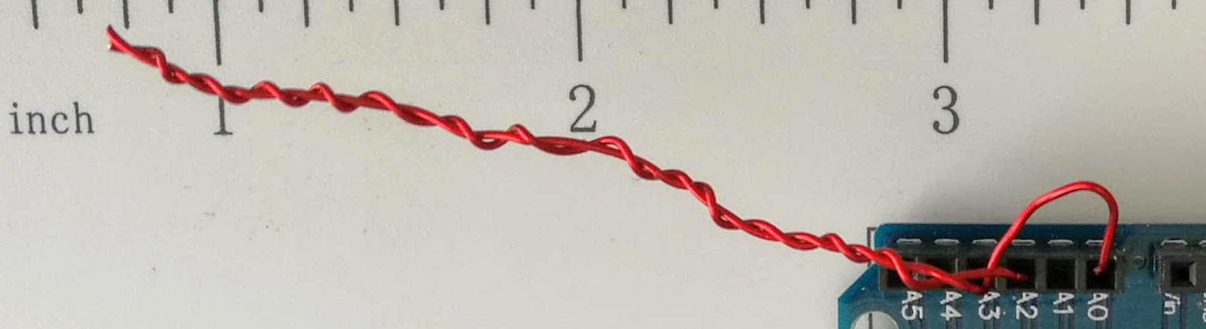
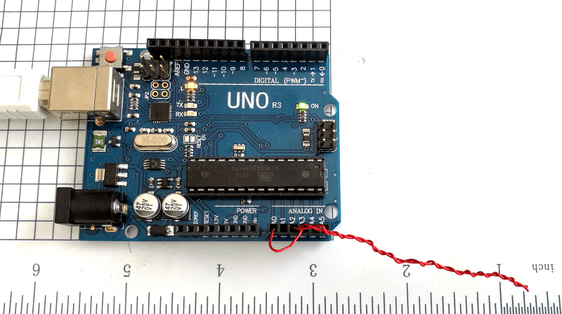
You can see I made a gimmick just bigger than two inches. I then went looking for something around the lab that had the ability to measure such a small capacitor. The component tester couldn’t. I have a nice digital multimeter that has a special plug-in for measuring capacitors and thermocouples, but it wouldn’t reliably read anything under 25 pF. I was thinking about building up a circuit to test when I realized I should search Hackaday first.
Hackaday Saves the Day
[Jonathan’s] capacitance meter is just what I needed and I even threw it out to an Arduino that was already hooked up using the Arduino Create web interface, so that was easy. I actually used the newer “Mark II” code but it works the same for the low values I was measuring. I calibrated with a garden variety 10 pF ceramic. It probably isn’t that accurate, but I really only wanted to see the change more than the actual value, so I thought this was sufficient.
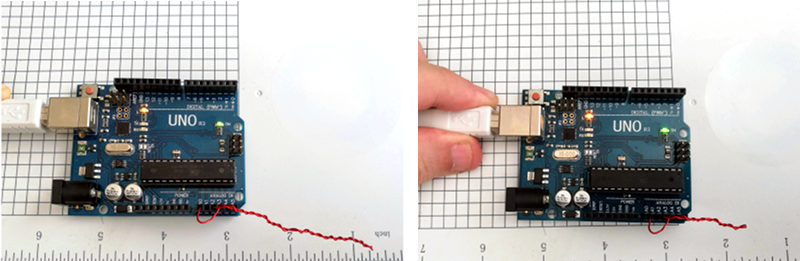
The two inch (call it 6 cm) gimmick reads about 5.5 pF. That might not be totally accurate, but I was expecting about 4.5 pF and the magnet wire insulation is quite thin, so it’s in the right ballpark. Let’s take it as a baseline to measure change. I then cut about 1.5 cm of the capacitor away — about 25% — and the reading became 3.7 pF. Another centimeter brought it down to 2.6 pF.
Of course, hand-wound pitch isn’t very accurate, nor were my cuts or measurements, but that works out to just around 1 pF per centimeter. Obviously, your results are going to depend on your winding and the kind of wire you use. [Harry Lythall] suggests folding a single piece of wire, holding it with pliers, and twisting. Then you cut the loop when you are done.
That’s a Wrap
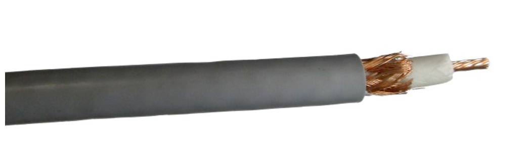 It is easy to forget that any two conductors near each other will have capacitance. Another common makeshift capacitor is a length of coax with connections at one end and open at the other. RG-8, for example, is about 30 pF per foot of cable. There’s even an online calculator that will tell you how much coax you need for any given value. This varies by coax type, of course, so remember to cut a little long and trim!
The next time you need a small adjustable capacitor — especially in a lab setting — don’t forget about the gimmick. Be sure to experiment with different kinds of wire if you are trying for larger values. We’ve seen this trick used in RF filters. In the case of the gimmick, you may be thinking small, but when you are really looking for high voltage capacitors, you can make those, too.


The problem with that technique is it is terrifically inconsistent and only works at lower frequency. As at higher frequency it is an antenna that radiates.
It may work in the ham world, but don’t plan on using in anything that needs multi band support or has a GPS. The harmonics generated will end up radiating and causing all sorts of problems for your high frequency radios
For clarity the on board Trace technique gets used all the time. The twisted pair technique is sketchy.
Depends on your definition of higher frequency. Hams have used these for years at VHF frequencies. Generally, if the frequency goes up, the capacity goes down and the wire length goes down, too. I would think in a lot of filter applications, the twist would be self-shielding. Don’t get me wrong, I would not put this in a piece of production gear (although it has been done). And, yeah, at what passes for high frequencies these days, probably not because the wire turns into 1/2 wavelength. But that’s not the whole world.
Google VHF gimmick capacitor and you’ll see a few examples.
http://www.arrl.org/files/file/Technology/tis/info/pdf/9712039.pdf for one.
Do you think certain geometries, certain ways of winding the wires and shapes you put them in, could help with that? Capacitance is surely only effected by the usual things, plate size, closeness and dielectric.
What if you took your length of twisted wires, and made it loop? Join each wire together at both ends. Same amount of capacitive stuff, but would make quite a difference as an antenna. RF is something I know almost nothing about. What about a spiral? Basically a way of getting the antenna to act against itself, while the gimmick cap stays happily capacitating.
>”As at higher frequency it is an antenna that radiates.”
But since the “ground” plane goes along the antenna, wouldn’t the effective lenght of the antenna be very short?
For example, take a dipole antenna and flip the other leg up the same way. Doesn’t radiate much, does it?
http://www.qsl.net/kk4obi/Center-fed%20V-dipoles%20Horizontal.html
As the angle of the V-antenna decreases to zero, the SWR goes up to infinity. SWR measures how well the source impedance is matched with the antenna impedance and it should ideally be 1.0 – the higher it is, the less power is delivered to the antenna and therefore the less it can radiate.
This is NOT just useful at low frequency. The concept was taught to me personally, by an RF engineer who had been a principle design engineer on telemetry used on the Apollo program. I was a prototype tech in a microwave lab working on modulator for a massive TACAN transmitter to be used on a NATO base. In questioning the RF engineer about the use of “gimmick” caps he addmitted such items had even been used in the Apollo telemetry radios. Since then I encountered them in several types of RF test equipment. By definition the resultant values are just a few picofarad at best, so their usefulness is even more effective at higher frequencies than at lower. Their characteristics of emmission is that of any twisted pair. A common technique to reduce emmission as well as the effects of it from other sources.
Agree. I worked with high frequency equipment and found this same concept actually designed into the pcb.I thought it was a defect, seeing two strands of magnet wire twisted together but cut at the top, later to find that, no, this was intentional. Actually had a schematic symbol for it, I think it was a twisted pair symbol, been a very long time since I’ve worked with them and seen it used.
How much inductance would a long piece of wire like that have?
I’ve never seen gimmick capacitors as long as in the photos. They are short enough that they stand up by themselves. They aren’t about emulating a capacitor value you don’t have, but when you need a small value, maybe in part because you want to vary it.
There was a famous Hallicrafters shortwave receiver that had a gimmick capacitor in the IF, feedback from the plate to the grid to get some regeneration. Only a small value needed, two pieces of wire is cheaper than a trimmer.
The other place I’ve seen them is feeding an oscillator into another stage. You need a small value, and the wire makes it variable.
A variation is just bring apiece of wire close to the input of a stage, but that might not be physically stable.
Michael
No I would never use one that long in real life probably. I just wanted something easy to measure and show the effect of shortening it.
Oh wow… so that’s what it is!
I’ve seen these really short twisted wires on old junked PCB’s in the parts bin. I always thought there was something on the other end of that wire that was cut off before it was scrapped. I never realized it was this.
Sadly, I never bought those boards because they usually didn’t have what I was looking for.
Neat article, thanks makes sense like higher frequency systems traces as passive components also… I was thinking making a decade LCR box one of these days like a decade resistance box. I was thinking having to invest in standards in the future and having to read into more where maybe there is potential to refine the cheap LCR meters and use variable components also with some sort of calibration pre-use check. This would be another material resourceful cheap way.
With both of these, you’ll need to ensure the capacitor is electrically small as well (less than 1/10 of a wavelength). At high frequencies you’ll start to see transmission line effects.
Transmission line stubs can be used to emulate capacitive and inductive elements at high frequency. Unfortunately, they’re often narrow-band.
https://www.allaboutcircuits.com/technical-articles/learn-stub-tuning-with-a-smith-chart/
Kirchhoff’s Law thoughts and sharing an interesting link unfortunately noting only impedance in detail at higher frequencies since commented on also elsewhere (wondering about capacitance, inductance and reactance throughout the range of EMF/EMS): https://www.nature.com/articles/s41598-018-20239-x
There’s some inductance too, so don’t expect to measure a gimmick capacitor and replace it with a standard component and get the same results.
Of course, if you want to be in the modern era, you can always just use a digitally tunable cap: pSemi (formerly Peregrine Semi) has a really nice line of them available for dirt ($0.75 each in quantity 1), tunable at the pF level with an SPI interface. Usable well into the GHz range. They’re QFNs (obviously) so you need to design a board and have some soldering skills, but they’re nothing difficult.
It’s ridiculous that I can just go out and buy a chip that I can tune to an exact capacitance within 50 fF (!) for under a buck, but hey, that’s modern technology for you.
There’s also an art of using reverse biased leds as varicaps. Especially the older ones work great.
That is really crazy. I just did a quick search for “digital tunable capacitor” and came up with a couple more manufacturers. IXYS have some that might be awesome for ham radio.
They all seem to have “low” resolution, like 4-5 bits, but that’s probably good enough for tuning up antenna matching circuits across bands or dialing in rough filter cutoff frequencies.
What a cool device! Thanks for bringing it up.
This seems to be interesting :
https://www.mouser.co.uk/new/ixys-integrated-circuits/ixys-ncd2100-capacitor/
Wide capacitance range of 6.6pF to 37.553pF
0.063pF small step size
Digitally select up to 1024 capacitance values
Cheers
It’s a bit more complicated than that for the IXYS caps. Which isn’t really surprising because stacking 10-ish capacitors or more inside a chip is obviously going to give you buckets of parasitics.
Under 100-200 MHz they’re probably okay, but at UHF they’re, uh, not. That capacitance range at the 70 cm band isn’t 6.6 pF – 37.553 pF, for instance – it’s like ~6.6 pF to 70 pF, with gaps. See the capacitance vs. control code plot on slide 8? That’s at low frequencies. Know why there are 4 big steps down? Because they steered the biggest caps to be a bit too small at low frequencies so they wouldn’t be unusably awful at high frequency (still *bad* of course, I’m not sure what use a capacitor with a Q of like, 3-5 is).
The pSemi chips are much more regular, especially as a shunt cap, all the way up to ~GHz or so. Capacitance range at the 70 cm band is still within like, 5-10% of the low frequency range.
The nice thing about the pSemi devices is they have really good equivalent models for the chips, so it’s easy to steer the tuning range of the caps to exactly what you want by putting a fixed cap in series or parallel with it, although it’s important to remember that if you don’t void copper under the component pads for any large pads (i.e. a fixed capacitor/inductor/whatever) the parasitic capacitance there will be pretty darn significant (like ~pF level).
The IXYS ones are okay for ham frequencies up through VHF, but for the 70 cm band, you really would want the pSemi ones. The pSemi DTCs are like, 3-4x higher Q at high frequencies.
When I was a kid I made a crystal set using a tin can capacitor. I put aluminum foil on a piece of kraft paper, wrapped it in saran wrap, rolled it, and slid it into a tin can. You slid the paper in and out of the can to adjust the capacitance. The instructions were in one of those old Time-Life science books.
Did you use it for all the tuning? Or did you have the large wirewound inductor with a slider as well?
wow, this was a long time ago, I’m thinking back, the inductor was either a coil of magnet wire wrapped around a pencil. or possibly one of those old Radio Shaek variable indictors with the magnet on a long screw. Probably the former, I don’t think I had enough money for Radio Shack stuff at that age.
We needed a highly temperature stable capacitor for a converter and settled on some length of teflon coax
not exactly the same thing, but still even in some very expensive pieces of kit, DIY caps are being used
“There has been work on laying out linear capacitors on IC substrates using fractals, but we aren’t sure how that would translate into a PCB layout. We’ve seen lots of other PC trace components like antennas, shunt resistors, inductors, and transmission lines.”
You should look into various numerical and analytic methods for simulating these small capacitance values on the pcb. This is especially true at high frequencies. If you want accuracy, then you need a numerical method and you need to specify the pertinent characteristics of the materials. If you use a good method like FDTD or FEM and observe the results (E-fields/H-fields) visually, you will start to understand that components like inductors, capacitors, resistors are all very much alike at high frequencies, but differ only in the ratio of the materials involved. It takes some time and patience , but it can be very rewarding once it clicks mentally.
Take a look at OpenEMS (FDTD) for open-source.
Take a look at HFSS or High-Frequency-Structure-Simulator (FEM) for commercial if you have a lot of money. (faster).
“Of course, hand-wound pitch isn’t very accurate, nor were my cuts or measurements, but that works out to just around 1 pF per centimeter. Obviously, your results are going to depend on your winding and the kind of wire you use. [Harry Lythall] suggests folding a single piece of wire, holding it with pliers, and twisting. Then you cut the loop when you are done.”
Take long length of enameled magnet wire, fold in half, clamp loop end in vise or forcepts, other “ends” get clamped in drill chuck. Slowly twist to desired twist density, but taking care not to damage enamel. Cut loop end and strip leads on other ends. Test with capacitance meter. Calculate desired length for slightly more than desired capacitance length. Nip end to fine tune as needed in circuit.
Been quite a while, but I seem to recall noticing slots cut into ceramic disc caps, to trim their values.
Weren’t the slots in ceramic capacitors something to so with providing a path for arcing? There are special capacitors.
But I have seen hints about taking small ceramic capacitors and cutting them down to get a smaller capacitor. But then the insides are open to humidity. Maybe I read you could use epoxy to cover things up. It’s like filing resistors to get a different value, a possibility, but only in emergencies.
Michael
IF memory serves. I believe that the cut caps (slotted and edge trimmed) were in the very lowest cost RC cars, back in the 1980’s. These were toys that kids destroyed in a week or two, so I’d guess the life span of the caps probably wasn’t deemed as very important when based on the expected life span of the toys.
I only made a few simple repairs such as perhaps re-soldering broken connections and melting/stitching minor cracks of the plastics of any runners.
I then gave them to friends with kids.
I sort of miss getting those boxes of Radio shack culls!
Cordless phones & clock radios that were dropping victims, often made for easy repairs to a cracked pc board.
Does the capacitance change if you flex that twisted pair?
Wonder if that’d be a cheap way to measure how much a robot’s arm has flexed….