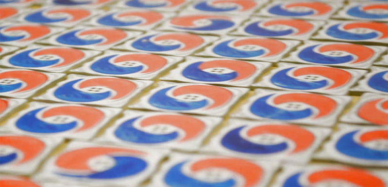
I’ve done a few experiments in adding color to printed circuit boards. These experiments used a process known as pad printing, and so far all indications are that pad printing is a viable process for truly multicolor artistic PCBs. For this year’s DEF CON, I’m stepping things up and taking them to their logical conclusion. I’m making true multicolor PCBs with orange and blue ink. This is, I believe, the first time this has ever been done with printed circuit board art, and it is certainly the first time it has ever been documented.
You may be wondering why I need more color on my boards. It’s that time of year again where PCB artisans all around the world are gearing up for badgecon DEF CON. For the last few years, independent badge makers have come together to form a demoscene of hardware creation. This year, add-ons for badges are a thing, and everyone is getting in on the game. Tindie is filled with amazing electronic badges and add-ons that will be found at this year’s DEF CON. There are badges featuring the Cromulon from Rick and Morty, baby Benders from Futurama, pikachus, and glowing tacos.
This is all about badge art, but when it comes to rendering an image in fiberglass and soldermask, everyone is working with a limited palette. Yes, you can get pink and orange soldermask, but I can’t find a place that will do it inexpensively. For any PCB, your choice of colors are only green, red, yellow, blue, purple, black, or white. No, you can’t mix them.
But I want both orange and blue, on the same board, cheaply and easily — here’s how I did it.
The Idea Behind The Tide Pod Add-On
 If there’s one thing Millennials like, it’s avocado toast. And student loan debt. And smartphones, they can’t get their faces out of those damn smartphones. Most of all, Millennials can’t get enough Tide Pods. The Tide Pod Challenge is the biggest fad of the last few years, surpassing even fidget spinners as the most culturally relevant trend of this decade.
For this year’s DEF CON, I decided to turn the Tide Pod Challenge into a game. The goal is to eat as many Tide Pods as you can. You do this by plugging a Tide Pod into a badge that supports the Shitty Add-On spec. Each Tide Pod has an EPROM soldered to it, and this memory chip stores a unique serial number. When you plug the Tide Pod into a badge, this serial number is stored in a linked list where every item in the list contains the serial number and a hash of all the previous items in the list. This is a blockchain, by the way. I made a blockchain of people eating Tide Pods.
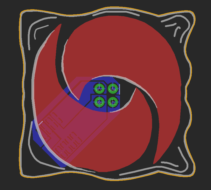
Since the Shitty Add-On spec provides power, ground, and an I2C bus, the implementation was very simple. All I needed was a small I2C EPROM. This is a 24C32, available from multiple manufacturers for $0.20, and is very close to being a jellybean part. The only other required part was the PCB itself. I quickly whipped up a design in Illustrator, taking care to make sure the blue and orange ‘swirls’ of the Tide Pod were identical and rotated 180 degrees from each other:

With the Tide Pod sketched out in Illustrator, turned into a simple PCB with Eagle, and a quick order from a Board House, I had a few hundred blank Tide Pods. The only thing left to do was add some color.
How to Buy and Operate a Manual Pad Printing Machine
I’ve written about the use of pad printers and their application to PCB art before, but the explanation of what a pad printer is and does was woefully incomplete. There was also no ‘guide’ to using pad printers, something I hope to correct with this post. For around $600 I ordered my pad printer as a ‘starter package’ from All American Manufacturing & Supply. This is not an endorsement of this company, and if anyone can find one, I’d really like a recommendation for a company that supplies instructions for their pad printing machines.
With that said, this is what a pad printer is, how it works, and how to use it.
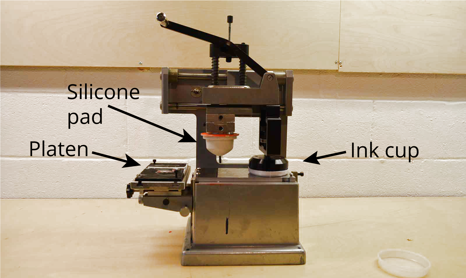
The pad printer I bought is a basic hand-operated system. There are four main parts — the platen, ink cup, silicone pad, and printing plate — all held together by a vast amount of cast aluminum.
- The ink cup: a steel cup with a ceramic lip that holds the ink against a printing plate.
- The printing plate: while not shown in the above image, is simply a photopolymer plate with a small impression of the desired image.
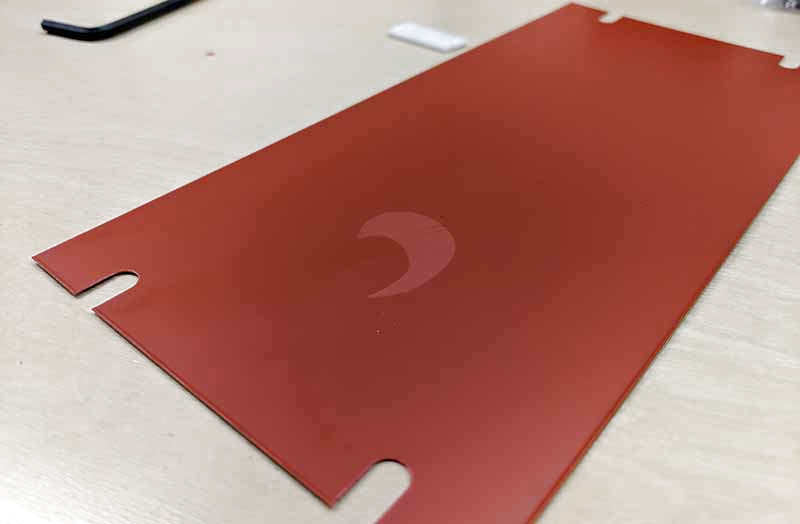
- The silicone pad: a flexible pad that transfers the ink
- The platen: a platform that holds the item to be printed
This is a clever and uncomplicated machine. The ink cup is attached to a moving arm that also holds a silicone pad. When the ink cup slides over the printing plate it deposits the ink. The silicone pad then presses against the plate, picks up the ink, and is moved over to the platen where it’s pressed against the object that will be printed on.
Step 1: Creating The Printing Plate
The printing plate, or ‘cliche’ in pad printing parlance, is a steel plate coated with a UV-sensitive photopolymer resin. There are two types of pad printing plates available from my supplier: water wash and alcohol wash. Water wash plates use water to wash away the unexposed photopolymer. Alcohol plates are washed in alcohol to remove unexposed photopolymer.
Simply for ease of developing, I’m using water wash plates, although this does have a few downsides: according to some documentation, water wash plates scratch more easily than alcohol wash plates. Also, water wash plates do not last as long; they’re only good for tens of thousands of impressions, whereas alcohol wash plates are good for a hundred thousand. In your home workshop, your arm is going to wear out before a water wash plate will.


To get the design onto the plate, I first printed the desired image on laser transparency film. I ran this through my laser printer three times to make sure it was sufficiently dark. After this, I peeled the protective sheet off the photopolymer plate, set down the laser printed mask, and put it in the UV plate exposure unit for 120 seconds. This plate exposure unit is simply a few UV fluorescent bulbs in a box with a timer; I’m certain you could also expose a plate with a few UV LEDs.
The instructions I found on the Internet told me to then expose the plate with the halftone pattern sheet. I don’t have experience in photolithography or printing technology otherwise, so I just put the halftone screen over the plate and put it back in the exposure unit for 30 seconds.
After the halftone screening, the plate was washed in warm running water for 2-3 minutes. The plate was then dried in a toaster oven set on ‘low’, and put back in the UV exposure unit for another 15 minutes. The result is the best plate I’ve ever made with this setup, and something that was good enough to make a few Tide pods.
Step 2: Printing With Pads
With the plate made, it’s time to mix some ink and fill the ink cup. The ink I’m using is Marabu Tampastar TPR. This ink comes in a wide variety of colors, and for future experiments, I can get this ink in Cyan, Magenta, Yellow, and Black. I plan to experiment with color mixing too, I just need to figure out what I want to print on a PCB.
Mixing up the ink is simple — Tampastar TPR ink is a ‘one component’ ink, that only requires thinner. I got out my scale and a paper cup, and mixed 25 grams of ink with three grams of thinner. This would have been enough for a thousand Tide Pods.


With a printing plate that was etched to the proper depth, printing went smoothly. There are a number of adjustments that have to be made to the pressure of the pad on the plate, the pressure of the pad on the tide pod, but this is a capable system that can easily transfer ink onto a PCB.
Is Pad Printing The Way Forward For Multicolor PCBs?
This is not a fast process. I ended up with about 250 Tide Pods printed with both colors, and about fifty more that I only printed in blue. The total time to get through 300 printings of blue was about three hours, or about 30 seconds per PCB. Since I was doing two colors, the total time was doubled, and I should have let the blue ink cure for at least 24 hours. Of course, this was a manual machine, and most pad printers are automatic. If you’re contracting this out, they will absolutely use an automatic machine.
For small production runs, this is a viable solution to the problem of creating multicolor PCBs. This was only my second time adding color to PCBs via pad printing, and even though I can see the mistakes — I didn’t let the blue dry long enough, I should have etched the pad a little deeper, and I should have laid these Tide Pods out to dry instead of throwing them in a bucket — I can see the promise here. If you’re looking for a viable way to add color to a PCB, pad printing can do it, and it can do it at a very low unit cost.


Surely there’s a niche here for the prototyping PCB services to offer a better range of ‘silkscreens’ and also multiple silkscreen layers. Wouldn’t a board with a white resist and then black and red silkscreens be great for battery projects with the big plus sign in red and the big minus sign in black?
Hmmm. PCBs as art. Making the non-conductive part clear (copper traces as a statement unto themselves), and edge-lighting with leds.
LEDs, that is what this badgette is missing!
Huh… Neat idea. Get some side-facing SMD LEDs and point them in toward the exposed circuit, framed by the solder ask of whatever color. Maybe even do cutouts in the circuit and use downward smd facing LEDs to shine through from the back.
Hint: Look into hot stamping too. No drying time, great durability and true chrome/gold.
How tough, and how durable are the inks, once fully cured? Can they handle washing the boards? With alcohol? What kind of resolution can you expect from the process? So many questions.
Pad printing, nice to see it done on PCB’s.
At first a was a little shocked by the cost of the “printer” but then I noticed the rigidity of the design. Meant to last forever.
I wonder if this can be created on the cheap, just for the fun on it… and while were at it… automating it in the process. Then again… I’m not making thousand of badges you I’ll think I pass this one.
Thanks for writing down the required processing steps.
I think because of the photolithographic process for creating the plate, it makes sense to sink some cash into the machine to have a good one. It’s already hard enough to get a great plate, you don’t want to be struggling with the ink transfer as well.
Since you had the UV lamp- Maribu has some UV cure inks that might have sped things up a little.
Pad printing is also a topic that in general could use the deepdive treatment, to support a manufacturing process that had pad printing the vendor came out and provided 2 days of training that still essentially amounted to the process basics and a warning that properly mixing the inks, modifiers, hardeners and thinner is a dark art that can vary depending on the temp and humidity…
“and if anyone can find one, I’d really like a recommendation for a company that supplies instructions for their pad printing machines.”
Here, more/less the same:
https://www.aliexpress.com/item/Manual-Pad-Printing-Machine-rubber-pads-and-custom-plate-die-Combo-3-in-1-printing-area/32866462810.html
But much cheaper. Of course the 600 USD one must be of Vastly Superior All American Quality®, but they both look very sturdy.
How to use it ? youtube instructions.
With the money spared, buy conductive ink.
Print a the circuit with conductive ink on a plastic badge. Conductive glue instead of solder paste, pick´n´place, no reflow / let dry.
Argh, damn you Benchoff!
Trolling even in the videos with your solitary all orange tide-pod pcbs (centre frame at 0:04 and again at 0:17) :^)