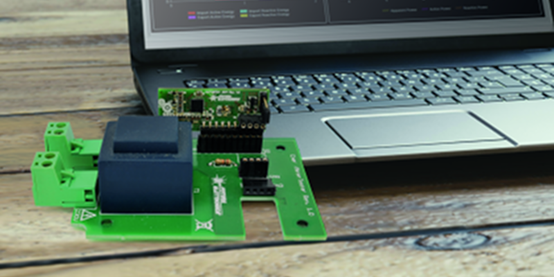
You would think that measuring a lot of sophisticated AC power parameters such as active and reactive power, RMS voltage and current, and line frequency would be a big job. As it turns out in so many cases, there’s a chip for that. The Microchip MCP39F511 can do all of that, but needs a little help from a few transformers. [Boris Landoni] has a two-part post that not only shows such a meter built with the chip but also has a very detailed description of the operation of the IC and how it works. The set-up takes two transformers. One to step the voltage down and another to measure the current.
Maybe it was just us, but we found the two schematics to be a little confusing. The schematic with two ICs on it is the actual board with the MCP39F511 (the other IC is a voltage regulator). The schematic with the transformer on it appears to have a single IC, U1, but that’s not really the case at all. U1 on that schematic is the entire circuit board from the first schematic. The “IC” pin numbers on the second schematic are the CN2 pins on the first schematic. The CN1 and CN2 on the two schematics are not related at all other than U1 is the actual board from the first schematic.
The second post is a bit less lethal since it covers the software although it wasn’t clear where to actually get the code. However, since the MCP39F511 has a simple register structure, you shouldn’t have any problem reading out the measurement parameters in your language of choice.
If you want to see another approach to energy metering, we’ve seen several other projects. Obviously, when you are working with the mains, you need to be careful.


I would love to have a tracking energy consumption!
“You would think that measuring a lot of sophisticated AC power parameters such as active and reactive power, RMS voltage and current, and line frequency would be a big job. As it turns out in so many cases, there’s a chip for that. ”
I think what some of the commercial units are doing is applying a bit of Neural Net to tease out individual devices signatures. Better than putting a monitor on each outlet.
I don’t know how they would do that. How would you tease out individual device signatures, when they’re all on line at the same time, in parallel? And even then, you’d need a database of all known devices, and even THEN all you’d get would be the “typical” characteristics for each, which is pretty useless.
You have a lot of loads that change in a house over the course of a day.
With logging and tracking it would be possible, if not exactly easy, to pick out when different appliances kick in, but without some kind of knowledge behind it, you would probably have to go over a few days and tag repeating things such as microwave, fridge, dishwasher…
Then all of the small incremental loads such as lights could be picked out.
I am sure there is a way to tell things like motors apart from transformers and electronics.
This is something that I have been thinking about for a while because I would like a nice panel-based meter of some kind that I could mount in or beside a main panel.
Google “energy disaggregation”.
It is cool to see how he is doing it, but there is no rocket science involved. And a much as I like building stuff, I am cheep and there are a lot of really inexpensive units out there that do exactly this that can be had for a couple of bucks. Even the commercial and I believe UL rated KillAwatt seems to be around $20 if you shop around.
What would be neat however, would be to make these with ESP8366’s and a cheep ADC, with no display, and priced under $10 a pop. That would let you monitor a lot of outlets and see all the results on one console. That would be neat.
Yes, that’s the way to do it. Unfortunately, this would require a LOT of devices, if every outlet you plug something into has to be covered. Might be better if circuit breakers could be made with this functionality. That, or current transformers could be mounted within the circuit breaker panel, on each branch circuit. Only two voltage sense transformers are needed, one for each incoming phase (since they may not be perfectly balanced).
Note that the current transformers can be of the clamp-on type, so this doesn’t require rewiring your whole breaker panel.
would want the granularity of per outlet but I would only monitor a hand full of things. 2 or 3 freezers, 1 AC’s, the fridge, some of the outlets in my shop, hi power but low duty cycle. I am pretty sure LED and CFL lamps are not going to be great big offenders. Things like ceiling fans might be interestign but they are hardwired.
This has been done so may times before.
Checkout the Open Energy Monitor project, which uses Arduino and runs on countless devices, not just AVR.
I’ve built multiple energy monitoring systems using the $2 BluePill STM32 board, a current clamp and a mains transformer (usually an old linear PSU), (plus a few resistors and capacitors to handle creating a small bais voltage so the input to the ADC never goes below 0V.
There are also loads of other power measurement ICs, if you don’t want to use a MCU to do the measurement.