Monitoring Energy Use And Saving Money

On the surface, the electric grid might seem like a solved piece of infrastructure. But there’s actually been a large amount of computerized modernization going in the background for the past decade or so. At a large scale this means automatic control of the grid, but for some electric utility customers like [Alex] this means the rates for electricity can change every hour based on demand. By keeping an eye on the current rate, you can extract the most value from these utilities.

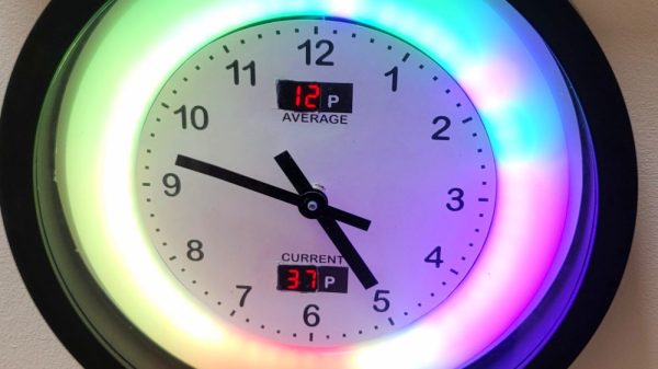
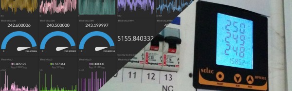
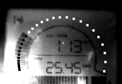
[Alex] is located in the United Kingdom and has an energy provider whose rates can change every half hour. This information is freely available well enough in advance to download the data and display it visibly in with a NeoPixel LED ring around a clock. The colors displayed by the LEDs represent an increase or decrease in price for the corresponding time and allow him to better plan out the household’s energy use for the day. The clock uses a TinyPICO ESP32 module to gather the data and handle the clock display. A second wall-mounted device shows real-time energy readings for both gas and electricity using two old analog voltmeters modified to display kilowatt-hours.

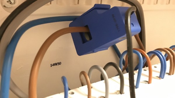
While not everyone has a utility which allows this sort of granularity with energy pricing, having one can make a bit of a difference as electricity rates under this system can sometimes go negative. [Alex] estimates that using these two displays to coordinate his energy usage has saved around £50 a month. Even if your utility offers minimal or no price adjustments for time-of-use, it’s still a good idea to monitor energy use in your home. Here’s a fairly comprehensive project that does that without modifying any existing wiring.

Building A Safe ESP32 Home Energy Monitor

The first step to reducing the energy consumption of your home is figuring out how much you actually use in the first place. After all, you need a baseline to compare against when you start making changes. But fiddling around with high voltage is something a lot of hackers will go out of their way to avoid. Luckily, as [Xavier Decuyper] explains, you can build a very robust DIY energy monitoring system without having to modify your AC wiring.

In the video after the break, [Xavier] goes over the theory of how it all works, but the short version is that you just need to use a Current Transformer (CT) sensor. These little devices clamp over an AC wire and detect how much current is passing through it via induction. In his case, he used a YHDC SCT-013-030 sensor that can measure up to 30 amps and costs about $12 USD. It outputs a voltage between 0 and 1 volts, which makes it extremely easy to read using the ADC of your favorite microcontroller.

Once you’ve got the CT sensor connected to your microcontroller, the rest really just depends on how far you want to take the software side of things. You could just log the current consumption to a plain text file if that’s your style, but [Xavier] wanted to challenge himself to develop a energy monitoring system that rivaled commercial offerings so he took the data and ran with it.

A good chunk of his write-up explains how the used Amazon Web Services (AWS) to process and ultimately display all the data he collects with his ESP32 energy monitor. Every 30 seconds, the hardware reports the current consumption to AWS through MQTT. The readings are stored in a database, and [Xavier] uses GraphQL and Dygraphs to generate visualizations. He even used Ionic to develop a cross-platform mobile application so he can fawn over his professional looking charts and graphs on the go.

We’ve already seen how carefully monitoring energy consumption can uncover some surprising trends, so if you want to go green and don’t have an optically coupled electricity meter, the CT sensor method might be just what you need.

Continue reading “Building A Safe ESP32 Home Energy Monitor”

Measuring Energy Consumption

You would think that measuring a lot of sophisticated AC power parameters such as active and reactive power, RMS voltage and current, and line frequency would be a big job. As it turns out in so many cases, there’s a chip for that. The Microchip MCP39F511 can do all of that, but needs a little help from a few transformers. [Boris Landoni] has a two-part post that not only shows such a meter built with the chip but also has a very detailed description of the operation of the IC and how it works. The set-up takes two transformers. One to step the voltage down and another to measure the current.

Maybe it was just us, but we found the two schematics to be a little confusing. The schematic with two ICs on it is the actual board with the MCP39F511 (the other IC is a voltage regulator). The schematic with the transformer on it appears to have a single IC, U1, but that’s not really the case at all. U1 on that schematic is the entire circuit board from the first schematic. The “IC” pin numbers on the second schematic are the CN2 pins on the first schematic. The CN1 and CN2 on the two schematics are not related at all other than U1 is the actual board from the first schematic.

Continue reading “Measuring Energy Consumption”

Meter All The Phases: Three Phase Energy Meter With OpenWrt

Keeping track your overall electricity usage is a good thing, and it’s even better if you know where all the kilowatt-hours are going. [Anurag Chugh’s] house has the three phases coming from the electrical distribution box tidily organized: One for the lighting and fans, one for household appliances, and one for the hot water supply. To monitor and analyze the electrical fingerprint of his house, [Anurag] installed a 3 phase energy meter and hooked it up to the internet.

Continue reading “Meter All The Phases: Three Phase Energy Meter With OpenWrt”

Reading Power Use Data With A Webcam And Python

As any hacker will attest to, whenever an important tool is missing, you might as well just build a new one! That’s the position that [Matt] found himself in when he was attempting to measure the power consumption at his parents’ house. He left the transmitter for the power meter at home, and so the logical thing to do was to set up a webcam and a python script to monitor his dad’s power meter instead of going back to get his.

The power meter that he had handy was a GEO Minim Electricity Monitor. He found it very difficult to extract the data directly from this particular meter, so instead of digging into any of the communications protocols int he meter, he set up a webcam in a box with an LED and monitored it with a specially-written Python script. The script is able to see the particulars of the meter, and then reports back to the computer with all of the relevant data. [Matt] has put this code up on his project site for anyone to use.

This is a great workaround that doesn’t involve delving too deep into the inner workings of the meter in question. You could always build your own power monitoring system though, if that’s more of your style!

A WiFi Home Power Meter

acFor his masters at Cornell, [Christopher McNally] designed a simple, non intrusive home power meter capable of doing everything a ‘smart meter’ can do – log power consumption throughout a home, and display a log of a home’s power consumption over WiFi. He’s even testing out some interesting ideas, like automatically detecting when specific devices turn on by reading the current data.

From [Chris]'[Jeramy] developed his system around the Arduino and a Ethernet shield, taking care of networking and choosing a micro, leaving him more time to develop the more interesting part of the project: sensing current. For this he used a small, clip-on current transducer. This sensor generates up to 10 VAC across a resistor, but the Arduino doesn’t play well with AC, requiring a small rectifier built around an op amp.

While the project works as a homebrew smart meter, [Jeramy] wasn’t able to automatically detect when certain devices were powered on. This is partly due to the fact that changes in current were only seen in magnitude and not waveform. Also, if two devices were powered on at the same time, the software would see that as a larger device that draws the sum of the current of two smaller devices. Still, [Jeramy] came up with a cheap way of metering power in any home, and the cost of his solution is cheaper than a lot of professional systems out there.

All the code, files, and design report are available on [Jeramy]’ git.

Monitoring Your Home Energy Use

[Dave’s] been elbow-deep in mains voltage while building this home energy monitoring rig. He started with an approach that is different from most we’ve seen before. He wanted a system that could make a linear measurement to keep the accuracy as high as possible. His first thought was to use a opto-isolated linear amplifier to measure voltage, but ended up altering that plan since he’s looking for digital values when all is said and done.

He’s using an ADC on the mains side of the interface board, then sending the digital values to an Arduino with opto-isolators to keep the high voltage separate from the low. This does complicate things a little bit, as he has low voltage rails on either side; 0V and 5V to run the ADC on the mains side, and separate 0V and 5V to run the Arduino. To solve the problem of accurate current measurement over the full range a house uses he opted for a Programmable Gain Amplifier. It’s addressed via SPI and allows him to adjust resolution to facilitate accurate measurement of very small currents. We think anyone who has tried to measure small appliances (like an alarm clock) with a Kill-A-Watt and gets a zero reading will appreciate this.

The Arduino sends data via a serial connection, which [Dave] is currently graphing using his laptop. It would be nice to see a simple web-server using the Ethernet shield (or a different board like the RPi) so you could log in from the couch and see what’s been going on with your home grid.