The oscilloscope is an essential tool of any electronics bench, and it is also an instrument whose capabilities have expanded exponentially over the decades. Your entirely analogue CRT ‘scope of a few decades ago has now been supplanted by a digital device that takes on many of the functions of both an expensive multimeter a frequency counter, and more. At the top end of the market the sky is the limit when it comes to budget, and the lower end stretches down to low-bandwidth devices based upon commodity microcontrollers for near-pocket-money prices.
These super-cheap ‘scopes are usually sold as kits, and despite their very low bandwidth are surprisingly capable instruments with a useful feature set due to well-written software. I reviewed a typical model last year, and came away lamenting its lack of an internal battery and a decent quality probe. If only someone would produce an inexpensive miniature ‘scope with a decent bandwidth, decent probe, and an internal battery!
As it happens, I didn’t have long to wait for my wish to be satisfied, with news of the release of the DSO Nano 3. Let’s see what you can do with a portable scope for less than $50.
The Promise
Running across the DSO Nano 3 immediately raised an eyebrow. Here was a little pocket ‘scope from China with an internal battery, a proper probe, and most importantly, a claimed 20MHz bandwidth. Best of all, it could be had for a relatively paltry £36 ($47)! If it lived up to that bandwidth claim, it could be a real game changer, so I ordered one to give it a test. A few weeks’ wait for international parcel post, and I had the package on my bench.
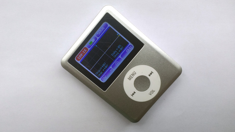
Surprisingly given that the trend has been for Chinese electronic products to arrive in ever-higher-quality boxes, this product arrived without packaging save for a plastic click-seal bag. Inside was an instruction sheet, a mini-USB lead, a ‘scope probe, a BNC to 3.5mm jack adapter, and the DSO Nano 3 itself. I could have been forgiven for thinking that I’d opened the wrong package, because that last item looked for all the world like a 3rd generation iPod Nano. Hence the name of the ‘scope, then. My best guess is that there is a factory somewhere knocking out fake iPods, and that their cases are available as components which make a handy enclosure for a pocket oscilloscope. I can’t imagine that it will please Apple’s lawyers, but either way it’s an interesting choice as a form factor for something that isn’t a music player, though not one without issues as we’ll come to in due course.
On the front of the unit are the same 2″ screen and wheel control that you will be used to from an iPod, and the similarity extends to the sides and rear of the unit. It’s worth saying that the wheel is a plastic one with a click action rather than the scroll wheel of the Apple original. I don’t remember the Apple music player having a USB Mini socket for charging, but I do recognise the 3.5mm headphone socket. There is a further rectangular opening on one edge that I suspect may have been used for a volume wheel on the knock-off iPod , here it is simply an opening through which you can see the PCB.
What’s Inside?
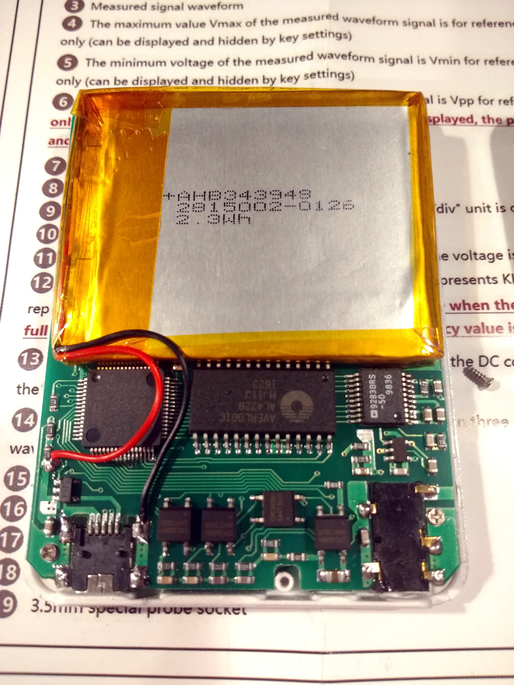
Opening up the device, most of its interior behind the display is taken up with a lithium-polymer cell, and space behind the controls is occupied by the electronics. There is a GigaDevice GD32F103 ARM Cortex M3 processor, an Averlogic AL4228 384k video frame buffer, a selection of CPC1008N (PDF) MOS switches, and an AD9283-50 50 Msamples/S analogue-to-digital converter.
The GD32F103 is the brains of the outfit, the AL4228 a piece of fast storage for keeping sampled waveforms, the CPC1008Ns switch between the various ranges, and the AD9283 is the analogue front end. This last part is slightly interesting, because unlike all the others which are of recent manufacture ours had a 1998 date code. How did a 20-year-old chip find its way into a 2018 device? It could be old stock, but I’d hazard a guess that it came from the huge Chinese market in salvaged electronic components that we have all read about.
It’s worth noting that the data lines of the USB port are connected to the GD32F103 despite the manual claiming that the socket has no function other than charging, and a quick look with lsusb revealing no device appearing. If anyone has any tips or tricks as to how this might be probed, let us know in the comments.
Using the ‘scope
Enough about the physical properties, what is it like in operation? Once I’d charged it with the USB lead from a wall wart as advised rather than a computer USB socket, I powered it up with a long press on the centre button. After the splash screen I was rewarded with an oscilloscope display. Connecting the probe to the 3.5mm socket with the supplied adapter, and with a bit of manipulation, I was able to display waveforms from the signal generator.
The interface having to stay within the constraints of the Apple-style click wheel meant that selecting different rages and probes was a frustrating process, but possible once you are used to it. As to its functionality, it lacks some of the advanced functions you might expect of a more accomplished ‘scope or even that which I found on the low-bandwidth model I reviewed, this is very much a basic instrument.
There are two basic functions that an oscilloscope should provide; accurate measurement of voltages, and of time periods. I proceeded to offer the DSO Nano 3 a series of test waveforms, and compare how it displayed them with the same waveforms as rendered by a RIGOL DS1054z. Nano 3 screenshots are all photographic, as mentioned earlier the USB port is purely for charging and does not mount anything from which you can grab an image.
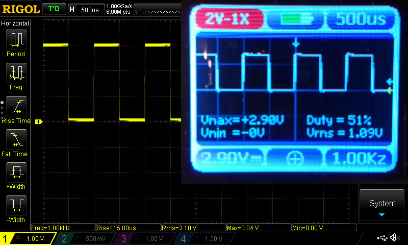
First order of the day was to hook it up to the Rigol’s calibration terminals (the DSO Nano 3 has no calibration terminal of its own). The Rigol supplies a 3V pk-pk 1kHz square wave designed for probe adjustment, and as with any new probe, this one would need a tweak. The adjustment capacitor is on the plug rather than the probe with this model, and unexpectedly needed little attention. With the square wave on the screen then, I could straight away see that the Nano 3 had its frequency as spot-on 1kHz, but the voltage calibration was significantly off at 2.90V to the Rigol’s 3.01V. This would prove to be a consistent issue across all readings, with particularly the RMS values of sine waves varying wildly from those measured on the more expensive instrument.
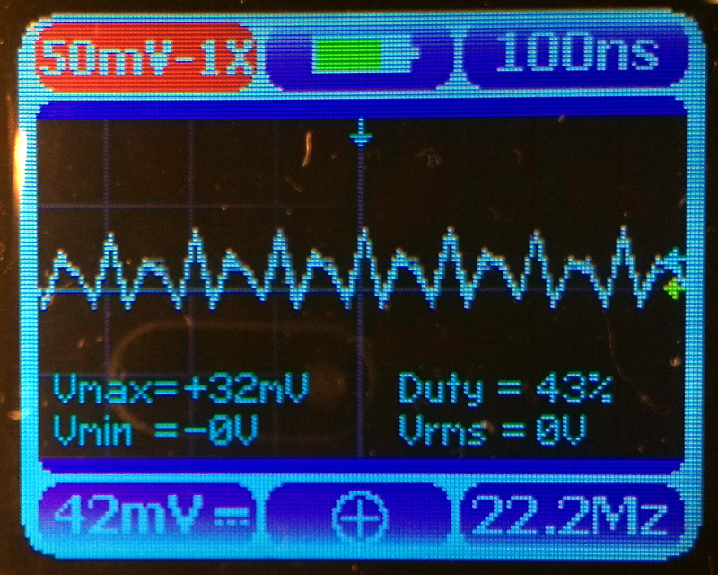
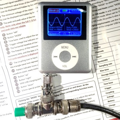
The party piece of this instrument though is that 20 MHz bandwidth. Firing up my venerable Advance RF signal generator, I set to feeding it signals through the MHz to see how it performed. All the voltages were adjusted to 100mV RMS using the Rigol as a monitor, and the feed came via a 50 ohm terminated co-ax line as shown in the picture near the top of the page.
Disappointingly, when fed a 20MHz sine wave the Nano 3 could barely resolve it. A jagged display was produced, with a very low amplitude and wildly varying frequency measurements. The shot on the left shows a reading of 22.2 MHz, it swung as low as 18 MHz as it tried to make sense of its input at this frequency.
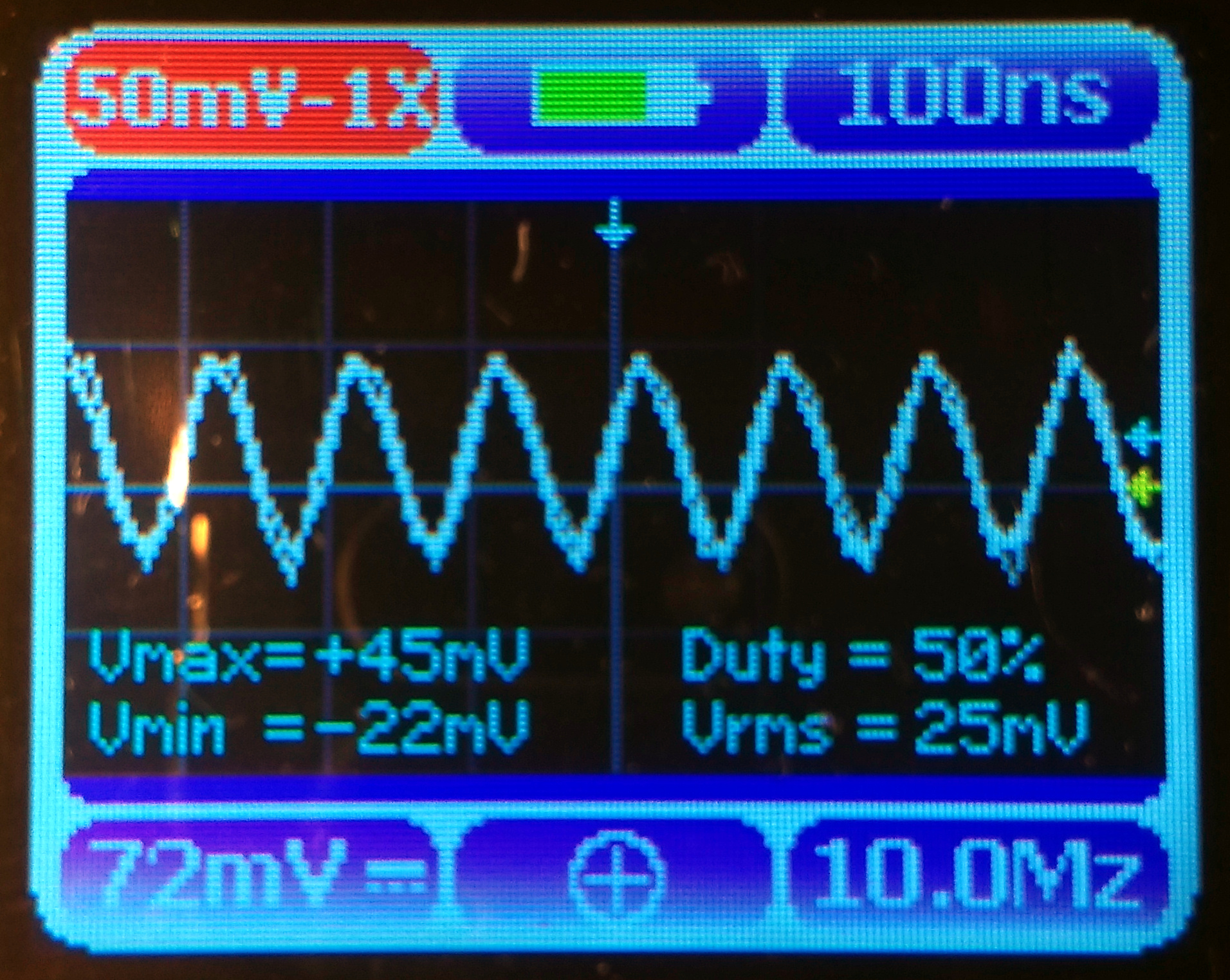
At 10 MHz the picture becomes a little better. The voltage is still way off, but something approaching a sine wave is appearing on the screen and it resolves the frequency correctly. All these readings are taken with the instrument set on a 1X range, as the input is from a 50 ohm terminated line and there is no attenuator present.
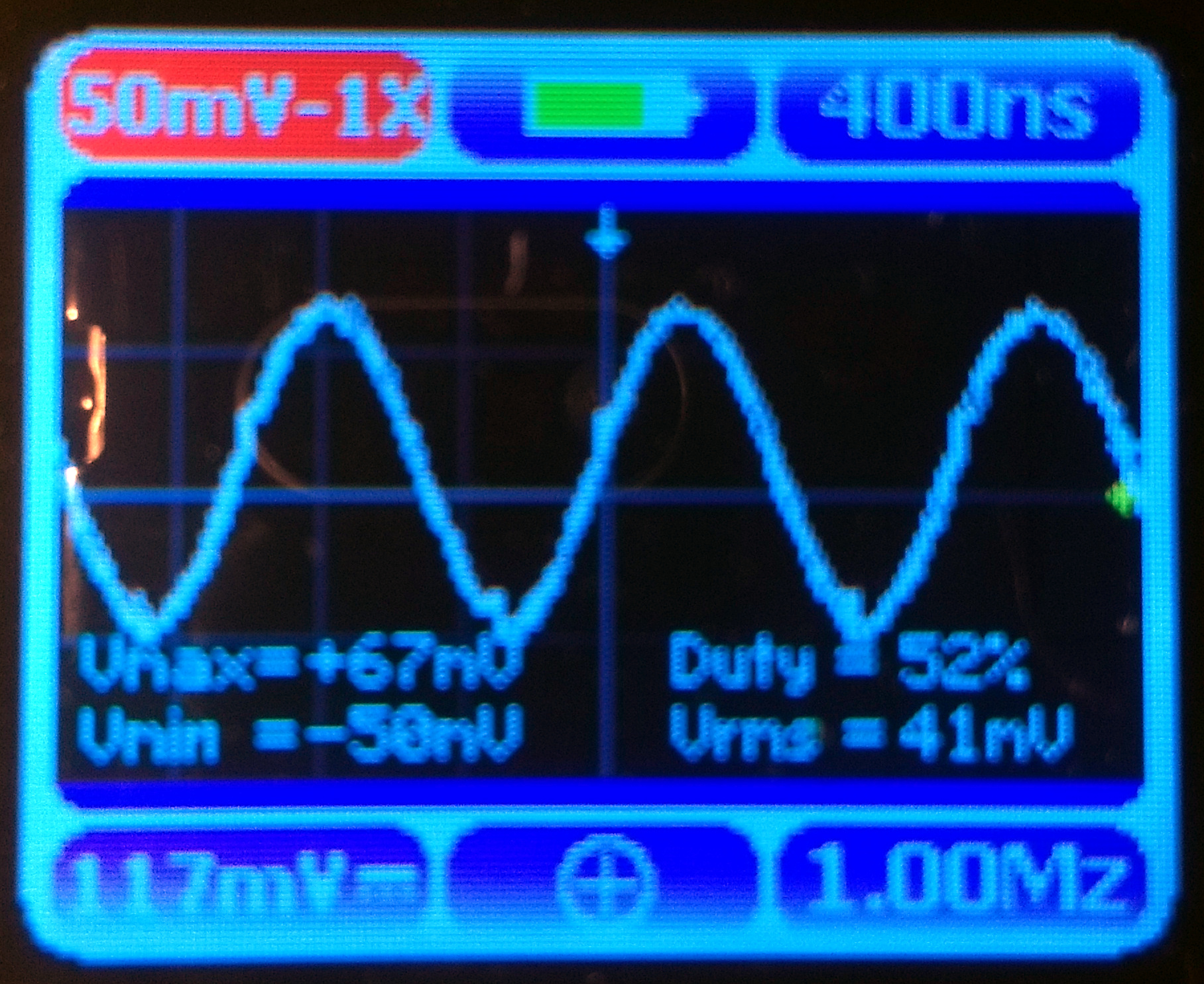
As the frequency drops below 10 MHz, the instrument starts to be a much more useful one. Our peak-to-peak voltages come closer to the 100mV set with the Rigol, and the waveforms look as they should. There are still some discrepancies in the voltage calibration, but this has become a much more believable device.
A Mixed Verdict
So having spent a while using the Nano 3, what do I think of it? The answer is extremely mixed, on one hand this is an amazing device that could truly redefine what a bargain basement pocket ‘scope delivers, yet on the other it manages to miss the target slightly with both its quirks and its shortcomings. Any such ‘scope that can break away from the few-hundred-kHz bandwidth of the other pocket ‘scopes has to be worth a look, but its over-optimistic bandwidth claim and consistent voltage calibration makes it not such an easy purchase decision, if its rather fiddly interface wasn’t enough.
The iPod case is a nice idea, but it seems as though for an oscilloscope to fit into it there have to be too many compromises made. If the mini-USB port was replaced with a micro-USB one, the 3.5mm socket with a BNC, the click wheel controls with something more useful, and some sort of voltage calibration curve applied, I could forget the 20MHz bandwidth claim and treat this as a rather nifty little 10MHz pocket ‘scope. But as it is I could only recommend this to you if you really must have a way to see a 10 MHz waveform that can fit in a tiny space at all costs. I recommended a novice buy the low-bandwidth ‘scope but I can’t make the same suggestion with this model.
Maybe it’s best to see this device as a first go, a herald of better ones to come. Even with this hardware there are sure to be ways that some of its shortcomings could be addressed in software, so when the inevitable copy-cat instruments and subsequent versions appear, perhaps they’ll be a lot more useful. I hope so, nothing says geek chic more than pulling out what appears to be an iPod and checking a waveform on it!


A lot of the other DSO Nano scopes have been rumored to be based off of MP3 players, but this is the most blatant yet.
Is an oxcilloscope an oscilloscope that is about as smart as an ox?
I’m pretty sure I’ve got this exact MP3 player kicking around, anyone uploaded the scope firmware yet? LOL
Be good if you could hotswap between that and, say, Rockbox…
It seems fair to say that the DSO Quad is twice as good for only 5 times the money. (I actually rather like mine, though default to the cute semi-retro Tek 336 that lives on the window sill above my bench.
“semi-retro Tek 336”. Hate to break it to you, but that and any ‘scope with a CRT display ARE retro!
Hey! The 336 has on-screen menus and all mod cons. (really cute, reminds me of “Asteroids”)
The DSO Quad and the 336 both have one important feature for me, both are motorcycle-portable.
Good to see there’s at least one other person who has motorcycle portability on their list of necessary features for electronics :)
Frame / suspension / wheel / tyre strength notwithstanding, anything’s motorcycle portable if you’re suitably ingenious ;)
… but are they Ner-a-car portable?
The Ner-a-Car has a nice big rack. It could probably manage a Tek 5440 mainframe. Though the lack of any rear suspension might not do the scope any favours.
I had a DSO Quad and it was only just good enough for my hobbyist needs. They never fixed the triggering bugs on the early hardware revisions. Luckily it broke recently and I’ve ordered a DS1054Z
Not a bad pricing for the kind of equipment they offer. Now what I really would like to see is the big names (Rigol, tektronix, etc) do some real oscilloscopes at that price point (or at least similar hardware).
Never happen, at least from Tek. Tek is not going to release anything at this pricepoint, they wont engineer something cheap so they would never recover their money.
A pattern generator would fit that form-factor well.
Is that 10MHz a real measured -3dB bandwidth?
A bit more info about the input section and voltage ranges would be welcomed.
How good is the triggering?
These cheap toys tend to forget about that.
I have bought (clones of) the DSO138 and DSO150 myself to play with.
The DSO138’s IU is horrible, and the DSO150 UI is usable, but unfortunately they cropped out on the software and the triggering is so badly designed and buggy that I also can’t recommend this one.
I was pleasantly surprized by the update rate of the screen though. Nice showcase for the STM32f103, and both have been uprgaded tgeneral purpose development kits with TFT for this processor.
You can’t find a cheaper development kit with TFT for any processor think.
DSO Quad also seems a no starter, because in that price range you do not have to put up with the crappy UI and small TFT because you can get a normal scope for around EUR200 with 10x or more the performance to value.
The only positive reviews about these things seem to be from peaople who do not own, nor have used, a normal oscilloscope.
There may be some niece applications where it’s small size and battery operation offset their disadvantages, but floating measurements on HV circuits with such a toy? Darwin willget you.
Buf for now I’ll stick to my good old Rigol DS1052E which is about the minimum of what would pass for a decent scope nowadays. I have been thinking about upgrading to a 4 channel Siglent xxxxX-E but I do not really do enough with electronics to justify that investment yet, but I probably will if I start seriously to design my own BLDC controller, which has been a dream project for me for 10 years or so for me.
Hear, hear. I bought a DSO203, claimed bandwidth of 72MHz. It is actually 72Msps, but some marketing wank at Seeed Studio wrote it down as MHz, and so everyone else copied it. The actual analog -3dB bandwidth is about 3.5MHz, born out by my calculations of the circuitry and tests by an author at EDN magazine.
The menu system is quite obtuse and nonobvious.
Good to know thanks for the heads up to both of you :)
Don’t see a link! Where can I buy one?
Look for DSO168 , it is the reviewed model’s moniker.
I guess the 20mhz is the sampling rate not the usable input signal frequency.
There would probably not be much interest in a scope that ony samles once every 50s.
i think you confused mhz with mHz?
Did you perhaps mean MHz?
You need 5 samples at a minimum to sample a sine wave (which will look like a pseudo triangle wave) so the 50 MSPS should have been the first clue that this was only a 10MHz scope. My 100MHz Rigol scope samples at 500 MSPS.
You need 2 samples if the filtering is perfect. A reconstructed wave that looks jagged (such as just drawing dot to dot) includes frequency components that are above the cut off.
This is incorrect. What if those samples all hit at the zero crossing?
Real world with real world filtering, I’d want sampling 5 to 10 times the -3dB analog bandwidth. And you want a bandwidth 10x the frequency of any square wave you want to look at, or your square waves look more like a sine wave.
I think someone viewing a 20MHz square wave on a 2GSps 200Mhz oscilloscope set to trigger on a zero level probably should have spent the money on something else.
:’))
This is absurd. Would you suggest, then, that if you have a 200 MHz scope on your bench, and you’re wanting to look at a 20 MHz signal, you should pull out your 50 MHz POS???
It is amazing how you read so much into what wasn’t said. You misunderstand me.
And BTW, the example of zero crossings had to do with the SAMPLING points, not the triggering. His point was that if you sample a sine wave at exactly twice its frequency, the indicated amplitude can be anywhere between zero and the actual amplitude, with the worst case being where the sampling point HAPPENS to occur at the zero crossings.
To avoid embarrassing oneself, one should ensure he understands what he’s ridiculing.
Well said, BrightBlueJim.
I just wanted to counterpoint Jeff’s comment. This is not why the DSO is a mess at 20MHz. When someone explained to me that drawing any wrong curve violates the bandwidth of the Nyquist limited data the light bulb in my head switched on. I don’t really care about the difference between 2.0000000 and 2.0000051; my point is that the requirement is 2 and not 5. Is the problem aliasing? I count 19 corners in the 20MHz test waveform in a 400ns period. This is quite close to expected for 50Msps. Sampling at 2.5 means it’s not aliasing. So is it a filter problem? Well, it’s being fed a 20MHz waveform from a signal generator. We know there are no >Nyquist signals, we are seeing data of almost half the height of the original waveform and there are limited ways a simple filter can screw up a pure sine wave so this is not a filter problem. Is it a noise problem? The wave produced looks pretty stable. Looks to me like the problem is the software.
Nyquist limits bandwidth to half your sampling frequency, but you can be arbitrarily close to it. For the limiting case as you approach the case you mentioned, you can still reconstruct the original sine wave with a sinc filter. In terms of real numbers, this is equal to fs/2, for the same reason 0.999… = 1
It doesn’t work in practice due to your finite sampling window causing spectral leakage, and due to your low quantisation SNR when everything is 0 (or infinitesimally small)
Sure, but in the real world, even in software, band limiting filters have rolloff, and ripple. Typically, the faster the rolloff, the more ripple is present. Same with reconstructions.
On top of that, I doubt a cheap pocket O’scope has really good reconstruction filters. From what I’ve seen, they end up with the skew-rate limiting the bandwidth on large signals, so every signal close to the limits looks like a triangle wave.
Yah… or so the digital fans keep insisting. From my perspective sample rate 10x max freq is acceptable.
The Nyquist criterion is > 2 samples per period. (not exactly 2 samples per period).
https://en.wikipedia.org/wiki/Nyquist%E2%80%93Shannon_sampling_theorem
And that’s a theoretical minimum, which is not the same as practical value.
Yes. No perfect filters. The highest frequency content of the signal must be >2f where f is the sampling frequency.
https://www.wescottdesign.com/articles/Sampling/sampling.pdf
With a perfect square wave (50/50 duty cycle), odd harmonics add to the frequency content. It takes at least the 9th harmonic to get a reasonable representation of a square wave. Make it a different duty cycle, and you must look at the shortest time between transitions to find the frequency of the harmonics.
f/2
Wow, did I muck that sentence up. Thank you for catching that. I wish it were possible to edit.
The highest frequency content of the signal must be <f/2 where f is the sampling frequency. A good rule of thumb is -60dB by the time you get to f/2.
< f/2
Before I bought my Rigoil 1054z, I was looking at handheld oscilloscopes. I might have bough a DSO Nano if it could handle higher voltages. I wish the screens were larger.
Well, technically, if you can manage 50M samples/sec, you can capture and display signals up to 25MHz in *some* form, so pedantically they’ve understated their device’s bandwidth, even though obviously 2.5 samples per cycle isn’t the best for 20MHz. Still if the reading is regularly wibbling 18~22MHz, you can split the difference and say it’s probably about 20MHz.
Seeing as I’ve recently seen people probing the finer video timing details of the Atari ST and apologising for their rather larger, more expensive logic analyser scope having rather less than perfect timing precision (on the order of about 25M samples/sec, which made the 8MHz and particularly 16MHz should-be-squarewave signals appear rather jittery and diagonal-edged), and the last “cheap” scope I saw and was considering investing in for some very basic analysis purposes was more around £90 (and eventually knocked down to £60, in the Maplin clearance), I’d be hard pressed to gripe about a 50M sample rate in a sub-£40 device, especially when buying electronics direct from China can be such a gamble and you might well just end up with a 2Gb MP3 player…
The wonky voltage reading is a bit more of an annoyance, but can’t it be adjusted in any way? If you’ve got an existing, moderately reliable voltmeter of some kind, just calibrate it against that and a fairly steady voltage source?
Question as a noob to this sort of thing, though – what would the min/max input voltages be? Is there an easy way to adjust the range of what you input to it to allow measurement of greater (or smaller!) voltages than what it can natively handle? I remember using different inputs or input adaptors on the old analogue school voltmeters so I expect it’s just a matter of some kind of resistor based voltage divider but the relevant physics classes were a good many years ago now…
Take a look at the Haasoscope. 125 Msps on 4 channels for about $100! It’s funded and available now. Open hardware and open source.
https://www.crowdsupply.com/andy-haas/haasoscope
https://goo.gl/1Ry1k4