FPGAs have gone from being a niche product for people with big budgets to something that every electronics experimenter ought to have in their toolbox. I am always surprised at how many people I meet who tell me they are interested in using FPGAs but they haven’t started. If you’ve been looking for an easy way to get started with FPGAs, Hackaday’s FPGA boot camp is for you. There’s even a Hackaday.io chat in the group specifically for FPGA talk for questions and general discussion!
While it is true FPGAs aren’t for everything, when you need them you really need them. Using FPGAs you can build logic circuits — not software simulations, but real circuits — and reap major performance benefits compared to a CPU. For digital signal processing, neural networks, or computer vision applications, being able to do everything essentially in parallel is a great benefit. Sometimes you just need the raw speed of a few logic gates compared to a CPU plodding methodically through code. We expect to see a lot more FPGA activity now that Arduino is in the game.
These boot camps gather together some of the material you seen spread over many articles here before, plus new material to flesh it out. It’s designed for you to work through more like a training class than just some text to read. There’s plenty of screenshots and even animations to help you see what you are supposed to be doing. You’ll be able to work with simulations to see how the circuits we talk about work, make changes, and see the results. We’ll focus on Verilog — at least for now — as it is close to C and easier for people who know C to pick up. Still not convinced? Let’s run though the gist of the boot camp series.
Both Simulation and Hardware
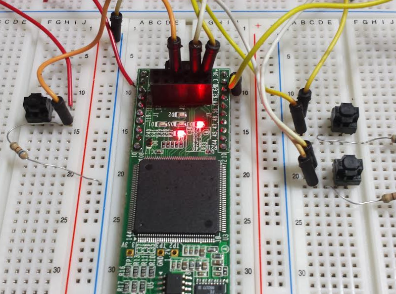
What hardware do you need? That depends. Right now we have four boot camps available and you only need real hardware for the final one. The inexpensive Lattice iCeStick demo board is great for your first adventure.
It is cheap (well under $30), has everything you need including a USB programming interface, and there are open source tools. So it makes sense to pick one of these up even if you want to move on to a different FPGA later. Besides, you can always repurpose the board as a logic analyzer once you’ve outgrown it. However, you can go through the first three with no hardware, and you can still follow along on number 4, even if you don’t have the hardware to do the actual work.
What You’ll Find In Each Boot Camp
If you know nothing about digital logic, you probably want to start with Boot Camp 0. By the time you are done with that, you should understand basic logic gates, combinatorial logic, flip flops, and sequential logic. There’s no real FPGA content there, and if you know the difference between a D and a JK flip flop, what setup and hold times are, and how to create a simple state machine, you can probably skip this one.
 Boot Camp 1 and Boot Camp 2 doesn’t directly use FPGA hardware. But they take you through building combinatorial and sequential circuits in Verilog. You can simulate your designs in your web browser or using an offline Verilog simulator.
In Boot Camp 3, you’ll actually move the Verilog into an FPGA configuration. You will need the hardware to get the most out of that. After that, there are some articles here on Hackaday.com about other projects with the same hardware that can take you even further along. The good thing is that until you reach the fourth boot camp, what you learn could apply to nearly any FPGA.
Let Us Know How the Tutorials Worked For You!
One thing that sets Hackaday and Hackaday.io apart is that we are a very interactive community. So in addition to the comments we are sure to get, we’d also like your help in a few other ways. If you work through these tutorials, keep track of how much time you’ve spent and let us know. We’ll eventually mark the times to help others plan in the future. In addition, let us know what else you’d like to see. Would you like to see new versions of bootcamp 3 for other FPGAs? Would you like more details about state machines, VHDL, or optimizing designs for timing? Leave your comments on the boot camp page, the tutorials page, or the FPGA chat and let us know what FPGA and non-FPGA topics you’d like to see covered in this format.


Wonder how many motherboards use them?
Generally the volumes for mother boards means they are likely to use ASICs if not just a totally custom IC. The workflow is pretty similar but instead of “programming” with a memory device, the chip is left unfinished and configuration involves creating custom masks and adding new layers to the IC — hard to do that for a handful. ASICs are cheaper in volume, start up instantly, and typically have lower power consumption than a similar FPGA. Because of the extraordinary cost of making a bad batch, you focus a lot more on testing, verification, and validation.
Isn’t that what they used for crypto currencies and sinclair computers?
I have been looking at getting into FPGAs for years.
But I always tumble onto a few problems.
There is no good IDEs to what I have found. Yes, learning Verilog or VHDL could work, but I would rather prefer something that were more graphics oriented and schematics based instead. I find it more logical and easier to work with. (If anyone knows of one, then please leave a link!) I also wouldn’t mind one where one can just “dive in” and configure each individual part of the FPGA individually, yes, this though might be very hard to implement and hand routing an FPGA is a non trivial task. (Though, yet again, if such a tool exists, then I have yet to find it.)
But my main problem is usually that most FPGAs that I have seen seems poorly implemented. Or I might just have a different idea of how programmable logic should work in hardware… Most FPGAs are capable of doing so much more then I need, and a simpler design could have done the same task with far fewer resources and done it with less delay and lower power demand as well. (While still being able to do the original “advanced” task without loosing performance compared to the original implementation…)
So well, I don’t use FPGAs mostly since I don’t think they are good…
(And 99.9% of what I do can be done with Microcontrollers and SoC anyway.)
A good state-machine editor.
Schematic capture exists in FPGA tools ISE did that pretty sure Vivado does not, Quartus prime seems to support it. Not sure why Xilinx doesn’t support this feature in Vivado.
Obviously Schematic capture doesn’t really scale to large devices so I guess they figured it wasn’t worth implementing.
It’s actually a real shame that Vivado doesn’t do Schematic Capture. I know educators who specifically choose Altera Hardware + Software because it has schematic capture. Others use Active-HDL to do schematic capture and conversion to HDL. Then use a synthesis / place & route tool of their choosing to map that to FPGAs.
Years ago I went through the same thinking. I know how to draw logic diagrams and had done so for years so why not do that. There are actually two reasons and I go into that in Boot camp #1.
Here’s the short version. First, you have to not think of Verilog (or the others) as a programming language even though there are some cases you can use them like that sort of. It is really a language for writing specifications. For example, I could draw up a multibit adder with XOR gates and AND gates — in fact, I show that in Bootcamp #1 in one of the side notes. But you shouldn’t. The tools have to work harder to realize that’s what you want. And if they know what you want they can do great things for you.
So in verilog if I write:
sum <= opa + opb;
The compiler might say "Oh, I have some dedicated hardware to do adds fast, so I'll use that." It might not figure that out if you've built your own adder out of gates. Granted, the schematic capture might have a way to either grab a "fast adder block" or attach an attribute to tell it what to do. But that's more work and not portable.
The second reason is, you get wiped out pretty quick drawing all those gates on anything non trivial. Let's say that I want to do that adder at gate level (and I won't use any of the function blocks; maybe for portability's sake, for example). We are going to do a 16-bit CPU so you'll need to draw a half adder and 15 full adders which is going to take some time. Oh wait, did I say 16-bit? I meant 32 bit. I can fix my Verilog code in about 3 seconds. It will take you awhile to add the other 16 full adders, even if you made a block for them.
Now thing about something only a little more complex like a 7-segment decoder. Not hard to draw out. But how easy in Verilog to just use a switch statement and explain what you want done.
So even though I was right with you, I came to realize after doing just some simple projects that HDL is your friend.
I don't suggest it, but there's always this: https://hackaday.com/2016/02/23/icestudio-an-open-source-graphical-fgpa-tool/
Try the bootcamps. You can do the first 3 with no hardware at all. I think you'll be surprised how much sense it makes once it clicks.
Mind if I tell you: Your example is of a very very primitive schematics capture tool.
Who makes an adder out of individual gates?! Of cores the tool should have an adder as a basic building block. (Since it is a basic building block…)
Same goes for buses, memory and so forth.
Yes, we can stroll into the land of gates when needed, but a good schematics tool shouldn’t need us to go that far unless we really wish to, or doing something very application specific.
So building a 16 bit adder should be nothing more then dropping in a full adder, specify that we don’t want a carry in, nor the two’s compliment implemented in our adder. And then it were done. (Just need to connect it to a few buses or buffers depending on our architecture)
Re specifying this to form a 32 bit or even a 256 bit system is nothing more then stating that we want a X bit adder instead. And we should preferably be able to set that as a variable for buses adders and so forth. So that we can make changes to our system more quickly.
And if we need to for an example get data from a specific bit in a parallel bus, then we just specify that as a constant (or from a point of reference like the LSB or MSB), and if this falls outside our bus, then yes we get an error, and that we would most likely get in any other hardware description language as well.
But in the end, a schematics tool can be just as powerful as any text based input method.
Since if there is a function in a text based programming language, then that can be a module for a schematics tool as well. (unless the function were purely syntax related.)
If current schematics capture tools aren’t having even the basics like an adder at current, then all I say is that they truly don’t live up to my standards.
Well, I agree it is a simple case, but I’m making a point. For example, I used to deal with the 68000 logic diagrams (I didn’t draw them). Huge pages with page after page after page of repetition. This was right when Kennedy tapes were just coming around so we still had paper everything and giant engineering copiers. So, sure, you can posit that your schematic editor will have all the things you need in it. Until it doesn’t. I have done it both ways and I’m telling you that while it is a system shock to switch, once you go to HDL you will wonder how you managed without it.
That a hardware description language executes in parallel isn’t a surprise, since it simply wouldn’t be able to describe hardware if it didn’t. (That I have never had any confusion about. And I have no problems wrapping my head around it either.)
But my point will still remain that anything one can do in a text based environment can be represented in a schematics. And vice versa.
The advantages with a schematics is that it is easier to overview and follow the flow of logic throughout one’s design.
And to answer your “So, sure, you can posit that your schematic editor will have all the things you need in it. Until it doesn’t.” I will only say, if you can write a piece of HDL code to describe logic, then we can just as well call that piece of code a “module” and have its inputs and outputs represented on a schematic’s object. So literally, whatever one can do in a text based hardware description language one can do in a schematics based one as well. (and vice versa)
Though yes, we can still create a library of premade modules for our schematics, these could for an example be small text files containing HDL code within them stored in some folder somewhere. And then we simply import these files into our project when needed. (And yes, libraries isn’t “special” for schematics tools, since libraries has existed in standard programming languages for ages.)
My point has never been that “I don’t want to learn any text based HDL!” since that is just dumb. My point is, there is no reason for why we couldn’t abstract the code into something that is easier to follow and trouble shoot.
But I see that you repeatedly insist that a schematics based environments inherently will have some lack of support and features and that it is simply better to go all out into the world of text. (And that statement doesn’t stand up to logic.)
Not to mention that there is no reason for a schematics tool to be static as in your example here:
“Oh wait, did I say 16-bit? I meant 32 bit. I can fix my Verilog code in about 3 seconds. It will take you awhile to add the other 16 full adders, even if you made a block for them.”
Since there is no reason for why a schematics can’t have a dynamic number of bits on different functions. And an adder is a fairly simple thing to make fully dynamic. (buses, registers, memory, and other bit-wise operations are though far easier since we typically don’t have to worry about a carry operation.)
And if we do something more advanced like a 7 segment decoder, then a look up table is fairly simple. And something we of cores would have support for in a schematics based environment.
Though, in the end, it doesn’t change my main reason for not working with FPGAs.
The main reason for why I don’t like Verilog or VHDL or any other text based hardware description language (or even programming language) is for the following reason:
I have Dyslexia, I can’t actually read. A and V are practically identical except for the little line on the A. Though, I still read almost as fast as avid readers, but text is nothing but squiggles unless I actively think about each character at a time. (Nice trait to have to not get lured by ads out on town, bad when trouble shooting code.)
This usually means I need to comment my code to oblivion and back, but a comment doesn’t say if I messed some little detail up in the actual code…
But looking at schematics I have a far easier time following along and understanding how it works. What things feeds into each other and so forth. So trouble shooting and error checking in this regard is not just a little easier and faster, but a lot.
I have no problem working with hardware description languages, nor do I have problems understanding how they work. It is simply that I can’t easily trouble shoot or work in a text based environment without spending most of my time searching for errors and bugs. The text could just as well be written in Braille, text just isn’t something I read subconsciously at a glance like normal people. (Some simple words I can do that with, but programming is just a blurb.)
@Alexander, I’ve just tried and it is indeed there. Quartus Prime has a pretty advanced schematic capture design entry. Maybe this could be your thing.
If I have a 16-bit adder as a module, I want to copy & paste a duplicate to get a 32-bit adder.
If I want 7-segment decoder, I want to drop in a box and refer to the 7447 chip. I don’t need to go further down than that.
When FPGA’s have Intellectual property (IP) issues, a whole slab of Verilog code can be represented by a simple box. If I want to replace that, it’s up to me to write the sub-modules that go in that box.
Schematics help show interconnection, abstraction, and reuse of modules. I could call modules “objects” and we could start talking about “object oriented” code here.
And here I see someone that understands what I mean.
Yes, a schematics based environment is technically nothing more then a graphical representation of code. And technically, we could translate between schematics and text without any side effect since they can both describe the exact same logic to the same degree. (in other words it is two sides of the same coin.)
A module in our schematics will have a set of inputs and a set of outputs, some code (most likely some HDL or more schematics modules) to describe how it works and nothing more special then that.
All though, I would consider it nicer if an adder were having a variable to state how many bits it contains, instead of needing to build it out of fixed modules. Since then we wouldn’t need more then to change the variable to change the size of our adder, and if that same variable states the size of our buses, registers and other bit-wise logic operations, then we could effectively dynamically change the number of bits our system is working with, without needing to fiddle around with anything but a single variable. (Unless our glue logic says no, but that it would also do in a text based environment.)
Though I think “Schematics help show interconnection, abstraction, and reuse of modules.” sums up why a way to look at code represented as schematics is a useful tool to have in a development environment.
It sounds like what you need is … the Vivado Block Design editor. It’s like a high-level schematic; it shows you connections between modules (and the implied data flow), but the modules are all HDL – the block design does not (and cannot) go down to the gate or LUT level.
One of the main reasons that Xilinx implemented the Block Design system was that keeping track of connections and data flow in HDL alone was becoming difficult for large designs.
@Evan
Seems like Xilinx had the same idea that I had….
Even though I wouldn’t mind if one could go to LUT level or gates, but well one can do that in HDL anyway, so the support is there. And as I have stated before, who would do things with individual gates… And it isn’t like the idea is to only work with schematics, but rather to use them to keep track of things and trouble shoot more easily.
Thanks, this seems rather perfect.
I think we’ve run out of reply levels so this is just a generic reply. I agree that you can go back and forth between HDL and schematics. And sure, a high level schematic has its uses. But if your top HDL is hard to understand then you’ve probably done it wrong, just like you draw a spaghetti schematic that is hard to read and understand, too.
I’ve made the mistake of using concrete examples that get latched on to, so let me try with some other thing. You’ve made a custom one-of-a-kind DSP algorithm. Your schematic editor doesn’t have it. So you draw up a slice and make it into a component. You do 16 bits (I’m going to stick with that example even though there are many other scenarios). Then you need 32 bits. Everything along the schematic chain is going to have to get bigger. You now must do a copy paste on everything in the input path, everything on the output path, and on your custom component. Impossible? No, of course not.
But if I’ve done my HDL right, I will go to one file and change a single define from 16 to 32 and I’m done. It is simply more productive. This is why professional mechanical CAD has gone to parametric ages ago. And maybe that’s an idea. If someone had a schematic editor that could do parametric design like Pro/e or some other CAD package you’d be on to something. At least for that case.
But then you have the other problems. So I’ve built a state machine and in testing I realize I want to add two states. Lots of work on a schematic. Trivial change in HDL. Same if I decide I don’t like an encoded state and I want to go one hot.
Here’s one more thought. Many tools do have schematic entry if you want to use it (or block diagram if you are on the recent Xilinx tools). You can mix and match. With most tools, you can even mix and match Verilog and VHDL if you like (two different HDLs). You can create schematic symbols from HDL and instantiate entities defined by schematics in HDL (because the tool probably converts them to an HDL subset anyway).
I shouldn’t complain. I also use emacs religiously because I use it and no matter how much better everyone tells me Eclipse is I only use it when I have no other choice. So I get it. But having dealt with very large digital designs in the real world (68000, 68HC11, some others you probably wouldn’t recognize) I can tell you schematics are to HDL what hand wiring is to PCBs. Sure, I can hand wire anything you can build on a PCB. But do I really want to?
Don’t worry. I am sure in no time someone will have a 2.5GB python library out there for FPGA so all the Python fanbois can call themselves FPGA programmers as well.
Hint, if your block of declared libraries is bigger than your actual code, you might not be an actual programmer
Also, schematic capture doesn’t really efficiently model the underlying hardware in an FPGA which is LUT or mux function-based. Even Verilog or VHDL aren’t that great a fit, being mostly designed for “real” hardware, but at least they can do look up tables if you choose. Honestly some modernized functional programming language, like a Haskell or Lisp derivative would probably be a great fit.
If FPGAs seems far to powerful for your needs, have you considered using a CPLD?
I’ve had good results with a numato Midas 2 board and free version on Xilinx ISE. Used it successfully for a work project. Even put a simple a soft up on it called a picoblaze. Works a treat and very inexpensive.
@Al, nice tutorial on how to get started. You always do good work on here. The only comment I have, and I realize it might be a bit out of scope for a boot-camp tutorial, but might be nice to add a small test-bench just to show of how easy is it is to use iverilog / GTKWave with the Project IceStorm tools?
I discovered Project IceStorm and ICE40 here on Hackaday a couple of years ago. I did some initial testing with the IceStick and discovered that the tools worked quite well. It was very nice to finally have a tool I could just use my preferred editor to work on code and then use ‘make’ without having to load a massive IDE. After that, I designed a board to interface the FMC bus on an stm32M4 series part to an 8K version of the ICE40 parts. While I thought 8K might be pretty limiting (based on previous experience with larger FPGA / IDE), I discovered that as I learned how to write better verilog, the resources required to get something done dropped dramatically and the estimated max clock freq increased. The other benefits of the ICE40 are of course very low current consumption and very low cost. I’m writing all this just to echo what Al already said. There is no reason left for anyone to avoid learning how to use an FPGA in their designs.
For those who are still thinking that they don’t need them, that may or may not be true, but one thing is certain: more and more parts are requiring high speed logic interfaces (high speed data converters for example) that you can’t just tie to general GPIO. Sure you can do a fair bit of DSP functions on an MCU with DSP co-processors, but intensive operations start adding up and eating all your cpu resources: FIR filters, decimation, interpolation, FFT, etc can all be efficiently handled in FPGA hardware. If you keep putting it off, you will end up playing catch up eventually. Just my 2 cents.
If you look in Bootcamp #1 this is already there. In the resources, I list Icarus and GTKWave as optional. There’s some mention at the front end:
I know some people don’t want to work on the Web or don’t want to create an account (honestly, though, this will just be tutorial code and making up a disposable e-mail address is easy enough). If you just can’t bear it, you can run all the examples on your desktop with Icarus Verilog (using GTKWave to display the results). I just won’t be talking about how to do that except briefly as an option in the very last step. You can read the Icarus introduction if you want to go that route. I still suggest you stick with EDAPlayground for the tutorial.
And the instructions part, step 9 tells you exactly what to do for Icarus/GTKWave.
If you don’t want to use EDAPlayground you can download Icarus Verilog or install it from a software repository.
If you want to use it, you’ll first want to save the files in the file section (design.v and testbench.v) to your working directory. Then you can use commands like this ….
Looking at it, though, I ought to put a screen shot of GTKWave in there (I just did). I think I might have had one once but we had a problem dropping some graphics.
So no, not out of scope at all. It was there all along ;-)
I apologize. I will admit I just looked at the file names and main Verilog briefly and didn’t notice the test bench. I did see where you covered the issues with syncing combinational logic with synchronous. I had a lot of issues with that to start with. I’m sure it will come up again for me at some point ;-)
No I’m glad you mentioned it. Made me add that screen shot ;-)
is math coprocessors why not fpga comprocessors in normal motherboard?
nigdy nie moglem tego zrozumiec
Intel must have bought Altera for something!
FPGA coprocessors have been used for at least 15 years
It’s worth looking at Verilator. It compiles to C++ code, which makes it run really fast compared to almost all the other simulators. It also allows you to write test benches in C++, which can be handy to emulate a complex system outside of your Verilog code.
Last time I looked, Icarus Verilog was a good bit behind Verilator in SystemVerilog support, too.
I have used Verilator. iVerilog also compiles — maybe just to C but that shouldn’t be an issue. If you ever notice, the simulation you run is just an executable although they have you run it through their starter to collect I/O etc. I used to use Cver a lot but I think it has not updated in a bit unless someone’s picked it up.
Also, Verilator is not always super friendly. They even say:
Now I do like dinotrace (also Veripool) but I seem to be the only one who doesn’t use gtkwave, so I used it instead).
https://en.wikipedia.org/wiki/List_of_HDL_simulators#Free_and_open-source_simulators
I have a Xilinx dev board that I’d like to employ, so thanks for the boot camps! I was stuck in OO programming mindset when I bought the board for my digital design course. Some sharper students used a familiar C environment then did some voodoo to turn it into HDL. It hasn’t been until working with PLCs that state machines and gate arrays started to make sense to me, so I definitely need to rehash the basics.
Thanks hack a day
In my recently published Amazon paperback “Build Your Own Computer – From Scratch”, I used schematic capture in Intel Quartus to design a CPU. There was a learning curve and a few missteps, but all-in-all Quartus did the job remarkably well. I chose the schematic approach thinking readers with little or no programming experience could more easily grasp the logic and computer design concepts.
If the authors of this tutorial are interested in copy-editorial comments, I have the following:
In paragraph 5 of section 3 of Bootcamp 0, “But if A is 1, the output is the inverts of B …,” “inverts” should be “inverse.”
Sooo is there anywhere the icestick can still be picked up for under $30? It seems to be a lot more than that now
Wow, the Lattice iCeStick is now $150, as of this post (June 2024)! Did Broadcom buy out Lattice?
I agree though: we need a low-cost alternative to the Lattice iCeStick for this Boot Camp.
There is a lower cost ICEStick alternative on ebay. I own it now and tried it.
It has an additional connector for 40 IOs as well I have not tried yet, as I would need the connector for the other end of the flex cable.
I actually modified some examples on nandland.com for this board.
The nandland GO Board is a good starting point. I did 8 of the projects there already.
https://www.ebay.co.uk/itm/127071780677
Just found exactly the same. Looks like Sparkfun have something similar; still not quite the $30 board of yesteryear though.
https://www.sparkfun.com/alchitry-cu-v2.html