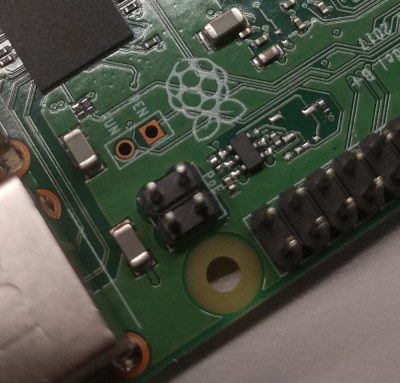
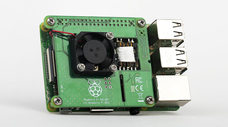
It was announced at the beginning of March, but now the Raspberry Pi Power over Ethernet (PoE) hat is out. Thanks to the addition of a new 4-pin header on the Raspberry Pi 3 Model B+, the Pis can get power from an Ethernet cable, provided you’ve got the setup to deliver PoE.
This is a remarkable bit of engineering, even though it’s just adding Power over Ethernet to a small single board computer. Mechanically, the PoE hat doesn’t increase the 3D bounding box volume of the Raspberry Pi at all. It adds cooling with a fan controlled over I2C. Even more bizarrely, the transformer is mounted in a PCB cutout, and we’re desperate to know how that was specced, designed, and assembled. Yeah, it might just be an add-on for the Raspberry Pi, but there’s some clever work that went into designing it.
 The Raspberry Pi gained PoE capability with the introduction of the Raspberry Pi 3 Model B+ last March, a release that did require a slight change to the hardware and pinout of the Raspberry Pi. Compared to the Pi 3 Model B, the Pi 3 Model B+ sports a four-pin header right next to the Ethernet jack and one of the mounting holes. This is the same location of the ‘Run’ header found in the Pi 3 Model B, and probably caused much consternation to anyone who built a hat to take advantage of having a real power button on their Pi.
Nevertheless, what’s done is done, and now we have a real PoE solution for the Raspberry Pi. This is bound to be a boon for anyone who wants to build a Raspberry Pi cluster computer, or anyone who is dropping a few Pis into a server rack that already has PoE hardware.
You can pick up a PoE Pi hat through the usual suspects (Farnell, RS, and other resellers) for $20.


I pre-ordered one of these. Was so annoyed when I realised it doesn’t pass-through the GPIO. Just what is the point?
…you buy pass-through headers…
The issue is that they could have designed it to allow easily for pass through headers. Instead you require an extended header for the GPIO pins and a smaller riser for the 4 Pin POE.
It does seem quite a design letdown seeing how many industrial reasons for using the RPi are for GPIO.
What in gods name are you talking about? Use this:
Here’s somebody who did the same thing with a ‘cluster’ hat. They (smartly) used 0x51 for the eeprom on the PoE hat, compared to 0x50 on most of all the other hats.
I mean, I just write bullshit on the Internet, but I’m not seeing a problem here.
The problem is, had they designed it properly to begin with, you wouldn’t need any additional hardware to pass-through the GPIO.
In reply to mark:
No the problem is that you are only thinking of your particular use-case and assuming that your use-case is the same as everyone elses. there are some people who use 90 degree connectors to bring the GPIO out of the side of the pi, were this hat to use extenders built in then it could throw off those users. So in reality, the proper design choice is to allow it to be end user configurable and thus provide a solution for the maximum number of users rather than do it one way and cut out a potential group of users. Stop being selfish, there is no benefit to excluding any one type of user when there are suitable mass produced adapters already available.
Hi Mike, thanks for attacking my motivations on a public forum where no one else was getting personal. Kudos to you.
Last time I checked the pi did not come with 90 degree headers as standard and so your example makes no sense at all as those users would need to be making modifications to begin with. And it’s safe to say that those requiring 90 degree headers would be in the minority anyway.
I have never suggested the PoE board use “extenders” but that the PoE board should pass through the GPIO, making the headers the same with or without the board.
That said, with the design the way it is, the solution Brian has posed would seem the best option, however it will make the assembly taller and therefore may make finding a case for it difficult.
and what about the fan ?
Isn’t the issue with the new 4 pin connector that there might be 42v on the network, and you don’t want that high a voltage on the GPIO header?
This is good and all, but when is there going to be a CM3+?
Ahh… no pictures of the interesting side ….
https://www.reddit.com/r/raspberry_pi/comments/99×117/more_information_on_the_raspberry_pi_poe_hat/e4rcg93/
Thanks,
awww, wouldn’t fit in my case :(
wonder if there’s a schematic, I could make a smaller profile one that’d fit… or I could not be lazy and figure out how to do it the old fasioned way but who am I kidding, I aint gonna do that lol
The centre taps are exposed from the 802.3af-compliant MagJack. You just need to add a couple of bridge rectifiers yourself and a chip for 802.3af identification and another chip that can handle buck conversion with a high-ish voltage input of 50-60 volts or so. (Nominally 48V but let’s be conservative.)
A $20 hat on a $35 micro. Urg. I thought these were supposed to be inexpensive.
Just be grateful you’re not australian… they’re $40 here plus shipping
i think all mine were around 50ish, because the brits seemed to have issues shipping to alaska, so i went with one of those ebay resellers that rip you off because it was cheeper.
“so i went with one of those ebay resellers that rip you off because it was cheeper.”
B^)
I’ve been waiting for this.
Now time to upgrade my Pi-Hole. I have a PoE switch for my security cameras, so using the PoE hat will mean one less wire in my rack.
Hmmm.. poopie hat… me thinks it is time to get a bit more serious in the names huh?
Nope
this is nice and all but i still want a decent battery supply thats intended for portable use. there are several ups type setups available for battery backup but they arent really designed for the long haul. the hackish battery system in my pi tablet leaves a lot to be desired.
Transformer in PCB cutout is quite common. Can just be placed like an smd abd reflow soldered in most cases.
@Brian Benchoff
It looks like the 4-pin header is next to the USB ports, not next to the ethernet jack like you wrote in the article.
@Brian Benchoff
Where is Hackaday Links?
Why not just get a PoE to USB adatper? Plenty exist. They make them for iPads, Google WiFi and other devices. You can get them with USB C connectors too. $10.58 on Amazon. https://www.amazon.com/UCTRONICS-802-3af-Splitter-Ethernet-Raspberry/dp/B01MDLUSE7/ref=sr_1_1_sspa?ie=UTF8&qid=1535374142&sr=8-1-spons&keywords=poe+to+usb+micro&psc=1
I have been using one of those for last 3 months, works without any problems. It’s pretty compact and price is decent.
I’ve been using this combo from Adafruit, works very well for what I’m doing for $8 (plus powersupply)
https://www.adafruit.com/product/2727 and https://www.adafruit.com/product/435
I don’t have a very long run, so the voltage drop isn’t a big deal. For runs over 50′ the real POE is the way to go.
No backwards compatibility with the Rasp. Pi, Rasp. Pi 2, Three?
How about an Ethernet version of the Pi Zero that’s not USB tethered for a network connection, not limited by a dodgy wireless chip, that includes 802.11af PoE?
The other point is that one hat for a single purpose is fine. Stacks of “hats” are a kludge waiting to happen. I vote for integrating some better functionalities into these boards…
That “dodgy” wifi chip on the pi zero is actually faster and more sensitive than the wifi chips on any of the various dell, laptops, apple laptops, asus chromebooks, and moto phones in this house.
You can wish for ARM chips that go into phones to have native ethernet, but it’s not gonna happen.
If you really feel this way, instead of voting, get to designing and see if you can do better.
Many arm chips for phones actually have an Ethernet Mac. The exynos series from Samsung for example, or many hisilicon and allwinner devices.
Many arm chips for phones actually have an Ethernet Mac. The exynos series from Samsung for example, or many hisilicon and allwinner devices.
It’s a shame with PoE+ supporting more then 25 watts you can’t get some of that 48 volt power directly. Either because of need for higher voltages or just for 10 more watts.
And the ATTINY is just for controlling the fan via I2C… And emulates the HAT EEPROM? And violates the spec “24Cxx type 3.3V I2C EEPROM must be used” ?
better interesting side picture https://raspberrypi.dk/wp-content/uploads/2018/03/pi-poe-hat-5.jpg
This must be an organic raspberry, because there is no pee in it.