In the past we’ve talked about one of the major downsides of working with vintage computer hardware, which of course is the fact you’re working with vintage computer hardware. The reality is that these machines were never designed to be up and running 20, 30, or even 40-odd years after they were manufactured. Components degrade and fail, and eventually you’re going to need to either find some way to keep your favorite classic computer up and running or relegate it to becoming a display piece on the shelf.
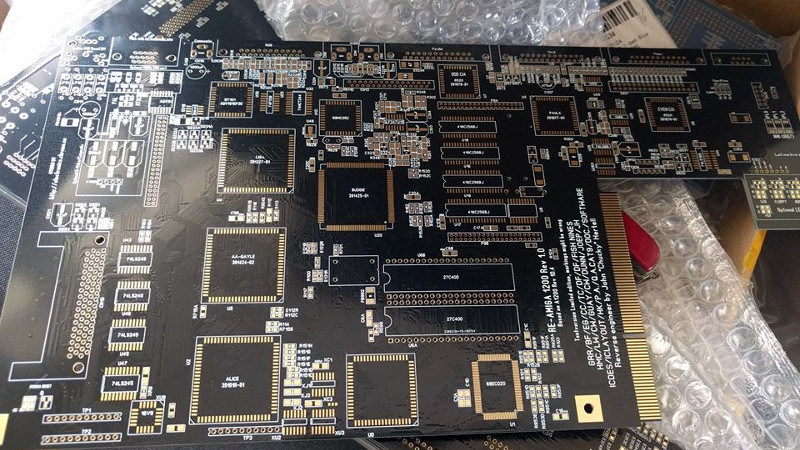
 If you’re like [John Hertell], you take the former option. Knowing that many an Amiga 1200 has gone to that great retrocomputing museum in the sky due to corroded PCBs, he decided to recreate the design from scans of an unpopulated board. While he was at it, he tacked on a few modern fixes and enhancements, earning his new project the moniker: “Re-Amiga 1200”.
To create this updated PCB, [John] took high quality scans of an original board and loaded them up into Sprint Layout, which allows you to freely draw your PCB design over the top of an existing image. While he admits the software isn’t ideal for new designs, the fact that he could literally trace the scan of the original board made it the ideal choice for this particular task.
After the base board was recreated in digital form, the next step was to improve on it. Parts which are now EOL and hard to come by got deleted in place of modern alternatives, power traces were made thicker, extra fan connectors were added, and of course he couldn’t miss the opportunity to add some additional status blinkenlights. [John] has released his Gerber files as well as a complete BOM if you want to make your own Re-Amiga, and says he’ll also be selling PCBs if you don’t want to go through the trouble of getting them fabricated.
It seems as if Amiga fans never say never, as this isn’t the first time we’ve seen one brought back from the brink of extinction by way of a modernized motherboard. Whatever it takes to keep the vintage computing dream alive.
[Thanks to Anders for the tip.]


I’m surprised that he started this project in June and now has a working board!
As I am not an Amigan, have USB devices (keyboard/Mouse/whatever) been adapted to Amiga?
What about newer disk drives, HDMI, or DRAM?
Yes they have, usb chips to the clock port, or even a usb to serial port adapter. Vampire upgrades allow hdmi and more. New Amiga’s being built. Tabor and Vampire v4, the x5000.
Also the X-Surf 100 Zorro ethernet card has an optional USB Rapid Road USB module.
I feel like this is only half the story. I’d like to hear about the components used, the special chips, the cpu, etc.
“The reality is that these machines were never designed to be up and running 20, 30, or even 40-odd years after they were manufactured.”
Pretty much true of consumer electronics in general.
The life expectancy is through the floor theses days thanks to RoHS, no lead in solder equates to “tin whiskers” and this is a 3-7 year lifetime at best on most of the current generation of hardware.
You know it is bad when tin whiskers can trigger false alarm in nuclear reactors:
“On April 17, 2005, Millstone unit 3 safely shut down without incident when a circuit board monitoring a steam pressure line short-circuited, which caused the board to malfunction and indicate an unsafe drop in pressure in the reactor’s steam system, when in reality there was no drop in steam pressure. The cause was attributed to tin whiskers on the board.” – https://en.wikipedia.org/wiki/Millstone_Nuclear_Power_Plant#Safety_and_environmental_events
I expect RoHS if it is forced on cars to eventually cause some major problems. Cars currently have somewhere between 30 to 100 microprocessor-controlled devices in them, and that will only increase over time.
You can always do an epoxy dip or something, i suppose. I wonder if some kind of procedure is in place after that reactor scare.
Are tin whiskers exclusively caused by lead-free solder, though? I’ve seen it on wire-wound devices. Or does the lead inhibit it through some kind of metallurgical alchemy?
In any case, I don’t think environmental regulation is even remotely to blame for shorter product lifespans. Consumer electronics are obsolete in tons of ways long before growing nanostructures short them out. Only weirdos like us still fiddle with the old stuff. Not that I don’t thoroughly enjoy it.
The exact science behind tin and zinc whiskers is still relatively obscure, probably a Nobel prize waiting to be collected by whoever fully demystifies it. I do not think that lead stops the formation of tin whiskers, but it does slow down their formation when added to solder.
Anything electronic in a car is coated with something – epoxy or whatever. It’s all got to survive extremes of temperature, moisture, etc. for the design life of the car which will likely be longer than the 3-5 years @Truth suggests is the tin-whisker limit.
The eutectic mixture used in lead-tin solder has stood the test of time with respect to inhibiting allotropic transformation of the tin. Electron microscopy of soldered joints on bronze artifacts unearthed in the nubian desert showed little tin whisker development after 1600 years.
Incidentally, pliny the elder in 79AD discussed the importance of getting the right eutectic mixture when soldering silverware.
That was your beloved tin-lead solder as it was and is used in critical installations. But you are simply clueless as usual.
Show me on the doll where “Truth” touched you.
Where is the redundancy, a single sensor failure causes a shutdown, if it didn’t report the correct pressure it could explode and the sensor would still report nominal values.. Way to go..
So you obviously have the figures from trusted sources right? Because even though some like to make these claims there are never any provided and verification. Why?
It is a lie. A lie as it isn’t supported from data. A lie as the industry have changed their practices to reduce the chance for tin whiskers (hint: coating), a lie as the lead free solders available have been tested and formulated to reduce the chance of tin whiskers. A lie as there are RoHS products are significantly older than 7 yyears, still in use and still working- I have a lot myself.
So now you have a choice to make: be a responsible grown-up and acknowledge that you are talking out of your ass, unless you actually have supporting material* that makes your wide claims true. Then I’ll admit I’m wrong.
(* given your sweeping statements that requires a lot, proof that life expectancy have been lowered and this due to RoHS, that the alloys used produces tin whiskers in real products, that 3-7 years life expectancy is true).
Yeah, there are so many reasons for lower lifespan of products nowadays. Underrated parts (especially capacitors), not designed to be repaired, and especially discontinuing software / cloud support. Compared to that any effect that RoHS has for general consumer products is probably insignificant.
Of course airplanes, cars, industrial equipment etc. could have higher demands for the solder and many of them have actually been excluded from the RoHS restrictions.
If you asked respectfully, and treated my like a human being, without accusing me of lying, I would have pointed you to some paywall info regarding 0.3 mm (WLP’s) and 0.4 mm pitch LBGA devices, but you can go off and find the current known problems for yourself. PCB conformal coating does not fix the problem, if does slow it down. Gold playing all solder joints does not fix the problem … If and when you start to treat others with some respect you might get some back, currently I think of you as a shill.
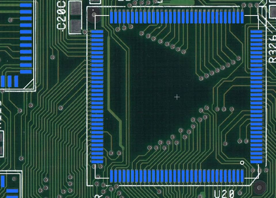
Another nice Amiga project! Wonder how the inner layers were re-created from those scans?
I’m guessing they weren’t, but auto-routed to make ends meet.
If you look at the gerber files, the section of the revamped composite output has four layers. The rest of it is all VCC or GND. Makes total sense, might as well use the rest of the layers if you need to have them anyway.
He simply beeped-out the inner layers with a continuity tester.
John ‘Chucky’ Hertell
“I have a lot of dead 1200s at home and leakage killed alot..”
:
Chucky is an amazing dude
That’s the way to do it. :)
Gotta love the dedication of the Amiga community!
For those interested in similar things I just found http://amigapcb.org/ which is pretty neat! It includes board diagrams/netlists etc of several different models and is like having the gerbers for the original pcbs!
Since the two biggest names effectively won (Apple and Intel). That puts everyone else in the nostalgia category. And yes it’s admirable.
Can you imagine breadboarding a prototype of the Amiga with 7400 series logic? Check out the image in this article of the original prototype. The article claims 7200 chips on breadboards!
https://arstechnica.com/gadgets/2007/08/a-history-of-the-amiga-part-3/
From the link:
“So there were three chips, and each chip took eight breadboards to simulate, about three feet by one and a half feet in size, arranged in a circular, spindle-like fashion so that all the ground wires could run down the center. Each board was populated with about 300 MSI logic chips, giving the entire unit about 7200 chips and an ungodly number of wires connecting them all. Constructing and debugging this maze of wires and chips was a painstaking and often stressful task. Wires could wiggle and lose their connections. A slip of a screwdriver could pull out dozens of wires, losing days of work. Or worse, a snippet of cut wire could fall inside the maze, causing random and inexplicable errors.”
Amiga Forever has some of that on their DVD.
For those kern to use FOSS tools, both gEDA PCB and pcb-rnd allow background images to be used when laying down tracks.. Here’s an example of pcb-rnd in action, with placement of parametric footprints, being used to clone the heyphone control board pcb
https://github.com/erichVK5/HeyphoneClone/blob/master/HeyphoneControlBoard.png
This could bring us to the next amazing project. An optical scanner picks up the position of all the pads and vias, then an automated flying probe tester creates the netlist from all the pads, and an autorouter recreates the layout from the pads and associated netlist. If only autorouters were better at making good layouts… Well, maybe with a hint of machine learning we will get better results in that field too.
This is the second modernisation of an Amiga product I’ve come across in just a couple of days (without even looking for anything Amiga). The first one was this Amiga 3000 inspired case that’s up on Kickstarter: https://www.kickstarter.com/projects/483774293/amiga-3000-inspired-modular-amiga-pc-desktop-compu
Although I backed the PC version myself, it is originally designed to accommodate an A500, A600 or A1200 board.
also check out http://www.amigaclub.be/projects/amiga1200plus
why just re-create the board, thats always a great idea. why not start making improvements? like a 68060 socket where the 68020 pad sits? this is silly… yet feasible with a controller… why not a 68040 where the 68881/68882 fpu pad sits? use the 68040 as a co-processor for the 68060, or is that impossible or even further from the purist side of the amiga? remove the board chip ram and add a ddr socket module for new and inexpensive ram furthering the capabilities. adding rtg to the board via fpga or modding the rom sets and using higher capacite IC’s or ROM. im all about new 1200 pcb’s no matter how you look at it, someone is going to say its too much work and most of what ive said is impossible…. no it isnt really, its all about finding someone capable enough to write bridge instructions/routines between processors and OS. im sure you could use your imagination youd tell me that nothing needs it….. why not write in the need on the controller? x processor does xa amount of work then off loads to y processor x amount until equal then x and y share between numeration; all built in, every program will use it, as for the OS write in fpu usage; Os doesnt use fpu numeration for anything, think of somethings that could use FPU usage, screen drawing, colour management (uses less memory, less seek time on read to draw back), higher graphic resolutions(lisa burns up at 1920×1080(hypothetical), well if the fpu is doing the work before lisa has to sync, less memory is used and the work is done) 24 bit colour native, use the fpu as a frame buffer in numeration and pass. even if one cpu is constantly handling fpu instructions or numeration through routine, the other is still available to do the work needed.
Why not do this. why not do that. simply: it is a lot of work.. then it would not simply be done.
it is not just to “put a 68040” onto the board. it is soo muchmore work. maybe later someday..
this however is to have a replacement of dead boards..
/John “Chucky” Hertell
of course its a lot of work, that was to be implied, what i was saying was, you have options to yourself. see the problem with most of you bloggers and other internet aficionados is that ppl like me strike cords in the right places and ask the most obvious of not obvious questions: why not further this type beyond the specifications in the places that make most sence? you arent wasting your time recreating this board, you are wasting your time through keeping your selves in the dark ages of these computers. they are already capable of what todays technology boasts, it was up to us to bring these computers up and sit them next to the “next generation, and to prove what they think they thought they had has been sitting right in front of their faces the whole time. this computer was discontinued to make room for this 3rd party reverse engineered garbage. why not allow yourself to take the time to step up this current state to a more feasible condition. if the market is deaming towards 040’s and 060’s, take that 20 off the board and recondition your strap until it meets those standards. give yourself options. you can already see other ppl are building 1200 boards, make your 1200 board the board they never expected. its all hersay and bullshit till its done by someone like me, i know this; however, if you though about this practically youd see that its going to cost you more looking for an 060 expansion board or a ppc board than it was to run the traces and offer at least an 040, at least the 040 has the option of upgrading to an 060 for a fraction of the cost it would take for you to motivate a full blizzard with a decent ppc and memory.
parts are inexpensive, memory modules are inexpensive, cpus arent quite as expensive as a new board that either needs the option or needs to be resold to make room for the board you wanted.
ddr memory would be a great addition, its inexpensive and outperforms simms.
look at this : https://www.retro-cloud.eu/shop/hardware-add-ons/atari-32-bit-family/ct60e/?v=7516fd43adaa
if they can do that for an atari falcon and make it inexpensive there is no reason something like it couldnt be created for the amiga.
Can someone post a link for the BOM for the 1200 build?