The HTC Vive Tracker adds real-world objects to your virtual world. While these real-world objects in virtual environments are now mostly limited to a Nintendo Zapper for a Duck Hunt clone and a tennis racket, the future is clear: we’re going to be playing Duck Hunt and Wii Sports while wearing headsets. The future is so bright, it burns.
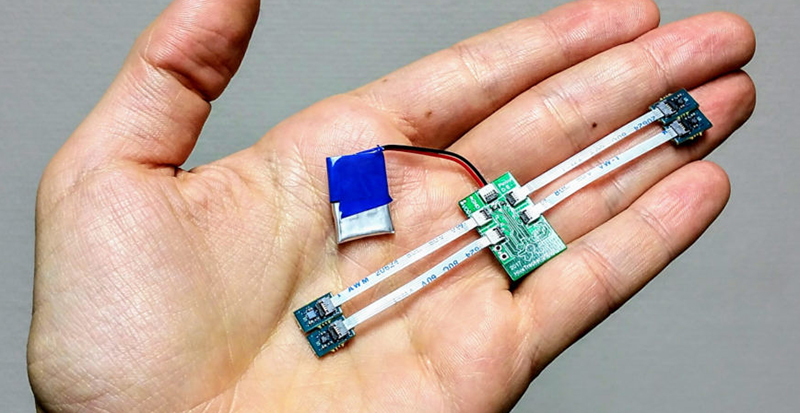
Of course, with any piece of neat computing hardware, there’s an opportunity for building an Open Source clone. That’s what [Drix] is doing with his Hackaday Prize entry. He’s created an Open Source Vive Tracker. It’s called the HiveTracker, and it is right now the best solution for tracking objects in a 3D space.
After a few missteps with ultrasonic and magnetic approaches, the team decided to piggyback on the HTC Vive lighthouses. These two base stations scan a laser beam across the room, first vertically, then horizontally. It’s an incredible piece of technology that [Alan Yates] talked about at the 2016 Hackaday Superconference.
While most microcontrollers don’t operate fast enough to see these laser sweeps, the team behind the HiveTracker found one microcontroller, with Bluetooth, and a feature called ‘PPI’. This programmable peripheral interconnect is kinda, sorta like a cross-bar, but designed for more real-time control of applications. With the right software, the team behind the HiveTracker was able to detect the lighthouses and send position and orientation data back to a computer.
This is a stupendous amount of work, and the results are remarkable. You can check out the video below and see that, yes, this is a real, Open Source Vive Tracker.


Um… search deep enough and you’ll find the plans and instructions for a Vive-compatible tracker that uses the lighthouse beams and can talk to a computer in real time. Its gotta be over a year old at this point. Might be a little bigger than what is seen here but it functions adequately and even has a BOM.
https://github.com/ashtuchkin/vive-diy-position-sensor was the first one I saw, always though this would catch faster the interest of DIY since you can even buy the lighthouse separately…
just put the direct link as a reply to this comment
Yes, plenty of projects do it, and we reference the best ones in the 1st log.
The main challenge in of this project was to miniaturize and ensure the parallel processing of several photodiodes, which must normally be done with fpga, but we found a trick ;)
Dig in the logs if you’re interested and feel free to ask if it’s not clear!
The main pic looks like a futuristic crown.
Anybody have any projects about a Free Open Source Kingdom?
:o)
Any hope for an open source base station? Would be neat for tracking robots or pets :)
That’s going to be the very hard part, I’m afraid. Those lighthouses are engineering marvels. But it should be attempted!
There is nothing particularly secret in the base station. However, the amount of mechanical engineering required to pull off one that is both reliable and accurate is likely beyond the possible for an average hobbyist. Just spend the hundred bucks and buy one – you won’t be able to make one at home for less than that anyway.
Yea, like trying to machine your own spinning VCR head assembly. :-) Best to just go out and buy one. :-)
Yeah, given that Valve had to go for custom motors and laser assemblies because of the shelf ones were not good enough, that would be pretty comparable.
I would say there is hope. The old design would have been much harder to implement than the new one. The latest lighthouse design uses a single rotor that projects a V shape beam and an array of LEDs for the omni-directional flash. Need a photodiode for synchronization and maybe another for sensing rotor speed and a motor driver to finish the design. Probably the best way to get someone to publish a design is to mention that you can probably implement the new version with a single 555 and some filters ;)
If you are up to it, go for it. The bigger the challenge, the bigger the glory!! (stark contrast from what I just posted, I know, but it depends on who’s doing it. Some squish spiders, other slay dragons. :-) )
Alan Yates mentioned being ok to help people who want to make a diy version but it would be less accurate…
Feel free to ping him on Twitter, he’s very helpful if you have reasonable questions ;)
This has serious usefulness for room-size 3d scanning. Knowing where the camera is with sub-millimeter precision could be very useful, especially since it could be done in the same room VR is done in. Make the room super plain looking and the cameras would generate less confusion. Make the walls green while you’re at it and the room becomes triple useful. :-)
Not really that much – notice that the gadget in the video uses 2 base stations (unlike Vive which works with even a single one) because they seem to be using the very basic & primitive triangulation calculation method instead of doing a proper perspective-n-points solution.
They also use only 4 sensors (the absolute minimum required), so any occlusion will throw it off (that’s the reason Vive has ~30 sensors and even the Tracker puck has more than 4). Worse, their HW design does not allow for more than 5 photodiodes which is going to seriously limit the tracking robustness of the device – a 6DOF tracker is rarely perfectly facing towards the base station during use. This is why the Valve’s design uses a small FPGA and not only a microcontroller.
Also the Vive/Tracker puck use sensor fusion to fuse the data from the on-board IMU with the laser system. The position/orientation is estimated from the IMU and corrected ~100x/second from the laser data – that has the advantage that the latency is much lower (you can get updated position/orientation even 1000x/second) and also that even when the laser beams get interrupted the tracking will continue just fine, at worst with a slight error. The HiveTracker has IMU on board but apparently not used yet.
And all this to achieve $60 BOM cost (not counting labor) – the original Tracker is about $90-$100, as sold to customers.
Anyhow, none of this is new, here is pretty much the same thing from 2 years ago, including full documentation:
https://github.com/ashtuchkin/vive-diy-position-sensor
from personal experience, the Vive system needs both lighthouses to track properly. (Also, it is best to turn them off when you are not using them if you want to watch 3d movies with a projector and active shutter glasses. They mess with the 3d system big-time :-) )
try turning one lighthouse off and watch the tracker continue to work as long as you are not standing in the line of sight.
The Vive system works just fine with a single base station as long as the HMD/Tracker puck/wand can “see” it. You won’t get as large tracked space and it will be less robust but it will work just fine otherwise. We have several Vives at work and this is a common situation. We have even used one with a single base station because of too cramped conditions for a public installation and it has worked fine.
What Valve likely does (and also Oculus – the math is the same, just it works in “reverse”) is that they carefully measure (calibrate) the mutual positions of the sensors on the surface of the HMD (or Tracker/wand). By knowing this 3D information you build a 3D model of sensor constellation. Then you can treat the base station as a virtual camera that “projects” these sensors along the rays you have determined by time measurement on a virtual “screen” at a fixed distance (virtual focal length), giving you 2D projections of the 3D points. And that is a standard perspective-from-points problem – if you know the 2D-3D point correspondences (which you do), you can use a bit of least squares math to estimate both the position and orientation of the sensor (or flashing LED in the Rift case) constellation. There are several well known algorithms for solving this, e.g. in OpenCV.
Another option is to treat the entire thing as an IMU augmented 6DOF SLAM problem. You base everything on the IMU data (including position estimation which would normally be unusable due to the extremely rapid error accumulation) and then correct this periodically from the measured beam intersections. That’s much more complex mathematically but potentially more robust because you could use even partial updates when e.g. only 2 or 3 sensors get hit by the beam. Such data would be ordinarily unusable (you need at least 4 hits to estimate a 6DOF pose) but e.g. extended Kalman filter can be “massaged” into being able to incorporate even such incomplete data.
However, most of the currently published hobby clones are physically unable to work with a single base because they use triangulation for each of the sensors individually – which needs two beams, one is not sufficient to obtain a position fix. That is very simple to calculate and even a microcontroller can do it, unlike the e.g. the SLAM solution above.
Nice explanation of the process. It will be interesting to see what makers/hackers do with this kind of technology down the road. ????
Only base might not be good enough for everybody:
https://www.youtube.com/watch?v=Uzv2H3PDPDg
The source article is also worth it:
http://doc-ok.org/?p=1478
For those interested in the reconstruction mentioned above, the excellent on this repo is worth it too:
https://github.com/cnlohr/libsurvive#lists-of-components
Inline responses to @janoc200 (using the ‘>’ character):
> notice that the gadget in the video uses 2 base stations (unlike Vive which works with even a single one) because they seem to be using the very basic & primitive triangulation calculation method instead of doing a proper perspective-n-points solution.
Ah, another fan of Inspector Gadget, happy to see that we share the same passion…
…but sorry to deceive, this is just a work in progress and nobody pretended to invent any algorithm here ;)
Obviously, it’s possible to use only 1 base, it would just be less accurate.
We would love to see pull requests from experts who can share their knowledge. This is an open source side project and the entire team is made of volunteers!
> They also use only 4 sensors (the absolute minimum required), so any occlusion will throw it off (that’s the reason Vive has ~30 sensors and even the Tracker puck has more than 4). Worse, their HW design does not allow for more than 5 photodiodes which is going to seriously limit the tracking robustness of the device…
That’s a deliberate choice, the original plan for this project was to miniaturize a tracker for use in neuroscience to allow 3D positioning of small rodents while simultaneously monitoring their brain activity and also as an alternative to expensive mo-cap systems for tracking small tools.
It would not help to put more photodiodes, as 1 is enough with a full IMU, so having 4 only makes it more reliable (+it helps for calibration, and tetraedric shape is practical).
Some quick characterizations are coming to the logs soon, but with our 1st Kalman fusion draft, the accuracy is still around 1mm even when all the photodiodes are occluded 95% of the time (627ms out of 660ms – we need 33ms for a full position estimation).
> This is why the Valve’s design uses a small FPGA and not only a microcontroller.
As mentioned in the logs too, the FPGA approach was the 1st idea, but we found a much cooler trick with the nRF52 PPI (see the logs), and it allowed saving space, cost and dev. time ;)
> Also the Vive/Tracker puck use sensor fusion to fuse the data from the on-board IMU with the laser system. The position/orientation is estimated from the IMU and corrected ~100x/second from the laser data – that has the advantage that the latency is much lower (you can get updated position/orientation even 1000x/second) and also that even when the laser beams get interrupted the tracking will continue just fine, at worst with a slight error. The HiveTracker has IMU on board but apparently not used yet.
We actually have a working fusion prototype which is way too messy to push now, but it’s true, it should be on github! (soon ;p)
…as mentioned above, we implemented the same principle and it’s coming! (it will always have possible improvements).
> And all this to achieve $60 BOM cost (not counting labor) – the original Tracker is about $90-$100, as sold to customers.
The $60 BOM was the unit cost for the 10 first prototypes, it can’t be compared with mass production ;p
In general, it’s not useful to over-optimize costs for the 1st prototype, but a new one is coming and it will be cheaper…
> Anyhow, none of this is new, here is pretty much the same thing from 2 years ago, including full documentation:
If you search, and read a bit more in the logs, you will notice that we actually started from the project you mentioned.
But nobody did this PPI trick in the radio chip, and nobody made such a small wireless tracker with parallel processing of multiple photodiodes ;)
Feel free to share it if you have any reference to the contrary, we could avoid spending so much energy for nothing…
And? How bright is The Future today?