When you’re debugging a board which has an ESP32, Raspberry Pi, or Arduino, it’s easy to slap on a small LCD display or connect via WiFi to see what’s wrong. At least, that’s what the kids are doing. But what if you’re old-school or you don’t have one of those pimped-out, steroid-filled boards? A resistor and an LED will often suffice. Powering the LED means one thing and not powering it means another. And with seven more LEDs you can even display 0-255 in binary.
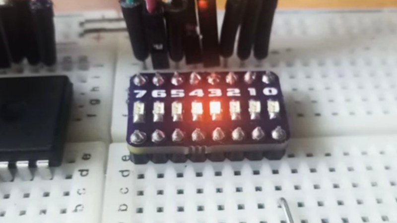
[Miguel] is clearly in the latter camp. To make debugging-with-LEDs easy, he’s come up with an 8-LED board complete with resistors. He’s even included the Gerber files needed for you to make your own. One row of pins are all connected together and the other row are not. So whether you’re using common cathode or common anode depends on how you orient the LEDs when you solder them in place. You might perhaps have one board of each type at the ready.
But who are we kidding? This is just plain fun to have on a breadboard. Show your prototype doohickey to a friend and you know they’ll be drawn to the little binary counter in the corner pulsing 42 or counting down until it starts flashing 255.
At risk of getting too feature-rich, you could then add two keys for a binary keyboard or add more LEDs to display 32-bit binary Unix Epoch time and see how long until your friends figure that one out.


Yes, really. I agree with told all above. Let’s discuss this question.
https://www.tindie.com/products/OwlLabs/led-diodes-debugger-shield-for-arduino/
Very similar to our design. We just put headers and created it as a shield. Your design is for bboard and ours as a shield. Good job! :)
I bought a few similar small led boards from Aliexpress a while back. Cheap as chips, but with the only difference that they have only one row as the cathodes are connected in common to one pin. These boards save me a lot of time when it come to debuging, as I don’t need to dig out a through hole led and suitable resistor from the drawer.
Perhaps these modules :
https://www.aliexpress.com/item/8-Bit-LED-Bar-Marquee-LED-Display-Module-with-4-Kinds-of-Color-for-Arduino-Low/32784458240.html
those are inverted and need vcc to work, not ground.
I made my own from cheap ali protoboard and some 0604 parts. very handy especially as i am trying to fix a digital pdp8/e…
Made something very similar too. Tied all the grounds together, put it on a 9th pin, making the whole thing inline on a breadboard, with only one ground connection. 1 kOhm resistors so that it works at any practical voltage. Done.
Very handy gizmo, despite its simplicity.
If you’re going to go to the effort of making a PCB then you might as well display hex on a couple of 7 segment displays.
Only if the 8 bits are supposed to make sense together. 8 separate LEDs has a place too, and is more “low level” on the sort of level working on a breadboard involves. Besides, this couldn’t be much simpler. Saves you having to work out the bits from the hex in your head each time it changes.
I have often wondered about a part like this but had no idea that it could look so cool.
well, most projects I do, work in the following order.
I starts with a simple LED, if I can make that blink, I know my program runs and that I can do IO.
Then I add serial to print some text.
And then I add a display, because that one is the most difficult and has too many things to go wrong. That is if you do it all from scratch, write you own display driver and initialization code.
In case you can use “off the shelf” code, like the arduino style coding of these modern times. Well then it makes sense to skip all the low level stuff, because then you can assume that the code (which comes from a functional library) is not a part of the problem when it doesn’t work…
Don’t need the PCB assembly. I used to work for a computer company in the days of blinkenlights. At some point it was decided that red was the wrong colour for blinkenlights because red indicates danger, or “stop”. We ECO’ed all of those red LEDs out for green (for “go”) ones. We ended up with thousands of red LEDs in the junk bins. Not just individual LEDs though, they came in blocks of four, with a built-in resistor and both anode and cathode leads available on a standard 0.1″ pinout grid. Every project any of us built for the next ten years or so had debug blinkenlights all over the place (until we inevitably got sick of seeing them :-) ). This must be a shared experience, surely?
That’s only slightly less stupid than Communist China switching all the traffic lights so that red meant “go”, which is probably an urban legend.
A blinkenlight doesn’t have any higher semantic meaning. It just means “1”. Means a voltage is present, from which you might wish to divine certain values and program statuses. The colour is absolutely the least relevant…
It was grown-ups who made this decision? I’m sure it certainly wasn’t programmers. It was one of those people who only noticed the colour of the LEDs, cos they had no other idea of what they actually meant, right?
Oooh, all those programmers on submarines, preserving their precious low-light vision. All the in-hide mainframes that hunters used to use. They’ll have been so angry about the change!
The fans on those 15″ racks would have made more noise than a whole fleet of submarines. :-)
Neat but a single-row vertical PCB would use a lot less breadboard space
It’s going to take 7 rows on the breadboard nonetheless.
Yes, but not 14!
Yeah, I don’t understand why have it take up 8×2 rows either. I would prefer it take 5×2. Should fit the LEDs. If you add a port on top for the common, you could get it down to 4×2. Not sure if the LEDs would fit. Most of what I do is chips so using an entire side wastes the same space.
Whuh? It needs 8 width cos there’s 8 pins for input. It needs the height because it has to span the gap in a breadboard, because that’s where the break in the contacts is. It couldn’t be any smaller.
Am I missing a joke? We all know what breadboard is, right?
How often are you connecting two bare breadboards (i.e. without voltage rails) together? Just curious…
That’s not 2 breadboards, the letters continue up. It’s just the gap in the middle of one. Yes I suppose you’re more likely to use one of the voltage rails as one of the connections, but you’d still need a gap for that distance. This thingy is just a little bit longer so you can also use it across the middle gap. Might be handy sometimes, for the extra millimetre or two, why not? How much shorter is the distance between the top or bottom rail, and the separate columns, anyway?
Here you go: https://github.com/therealprof/biledoctalboard
Also added more bells and whistles…
Post on hackaday.io
:)
https://hackaday.io/project/21468-led-diodes-debugger-shield-for-arduino
Have those bargraph blocks gone unobtainium or something?
No. This is that bit with integral resistors
Using SMD LEDs is probably smaller than a bargraph module anyway, since you need the PCB and resistors. That, and bargraphs are usually in groups of 10, not 8.
But but but…10 LED DIP 20 have been around forever. I have over 100 in tubes from an old project and just ordered more at 35 cents each. Here are some at a hobbyist shop https://www.jameco.com/z/LTA-10102KR-Lite-On-Electronics-ARRAY-10-BAR-GRAPH-SUPER-RED-0-20-HT-639nm-20-LEAD-2-6Vf-25_2227356.html
For switchable common-anode/cathode: remove the common connection from the PCB, and make an 8-pin jumper (solder-bridged berg strip) to plug into the breadboard on either side. As an additional bonus, you can unplug the jumper, and have individual connections for multiplexed drive or whatever. Just think, you can breadboard 7 of these, and charlieplex them from a single 8-pin port! (Tidy wiring left as an exercise for the reader.)
Or just don’t complicate things: stick either row of pins on either of the power rails and they’re automatically bridged together.
That was my first thought, too, but there’s a couple issues.
First, the power rails are in groups of 5 with spaces between; you’d have to use 2 4-pin headers, or a 9-pin header with one pin clipped. Takes up a little more space, and restricts where you can place it, but really? Not a problem.
Second, some breadboards have the power rails aligned with the grid, and some have them offset by a half-pitch (0.05″). So to serve everyone’s needs, you really need two versions. Still, if you happen to have breadboards of only one type, you can just make it to suit them.
Yeah but your 8-pin “jumper” is as much added complexity as any other option.
I suppose you could do something with bi-colour LEDs, so they’d work in either polarity, and some sort of diode arrangement. But again it’s adding more complexity, when half the use of this thing is it’s simplicity. It’s just meant to replace 8x separate LEDs, no more. If you wanted to you could add an OLED and a micro and have the thing measure current and enumerate USB, but that wouldn’t be 8x LEDs either.
If you really care about on-board commoning, prob best option is to do what the 7-segment LEDs do, and make 2 versions. Just put the LEDs the other way round in each.
I have a couple of this sort of assembly just on perfboard – old-skule LEDs and 1/4w resistors, and the pins are just the resistor leads sticking down, and a flying lead for common ground. Very handy.
Yah, had similar I made up for the breadboard “tool kit” some years ago, 3 moves since it hasn’t surfaced yet, so not sure if I’ve still got it somewhere or not.
Yeah, I’ve got stuff like that…
In 1973, seven-seg displays were still expensive, which is why Don Lancaster used a vertical row of incandescent bulbs for his RTL decade counter circuits. I built a racetrack timer using them.
But a little later, I found a company that made an itty-bitty decade counter circuit using a vertical column of four tiny LEDs, I built a six-digit counter-timer-frequency meter in a very cool 5″ x 5″ x 2″ enclosure. It worked great.
The most amazing thing to me was how quickly one can adapt to reading decimal digits displayed in binary. The pattern is very easy to learn. Even my kids — ages 12 and 9 — could read the thing on sight. Very cool.
For that reason, I’d suggest using a vertical 4-bit array instead of 8-bit displays. You can read the output as N hex digits.
Leibniz originally became interested with the idea of binary arithmetics by watching German dock workers use binary addition to sum large numbers for record keeping. Any idiot can count 1+1 = 11
They used binary? You’re not confusing that with unary, ie simple tallying? In binary, 1+1 = 10.
Likely the example is incorrect but the anecdote true. You can count up to 1023 on two hands with binary, a crowd-pleaser even for non-geeks
Pretty nice seeing someone write an article about what I did.
Now you’ll have to make more cool things. :)
I’ve been outputting binary for debugging on a single LED for years. You pulse the LED…a couple of blinks to catch your attention, then 1 second on = “1” 0.5 seconds on = “0”, with 0.5 second off’s between. Quick, easy, and needs nothing but an LED and a resistor. And a single IO pin….who has 8 pins for debugging?
This was suitable for me and my classmates in Digital Systems classes where you usually have several signal lines. Though it can be used in Microcontroller projects (there are several with tons of I/O) I can see your point.
And how is this not more complicated? It requires a timer and those might be even rarer than GPIOs. Not to mention that if your MCU halts (nah, never happens, just for theoreticals point sake) your interrupt handler will not fire anymore so blink code is no more which LEDs will often to continue showing the last state…
but for ultra coolness: i hust bought a HP 1600A Logic State Analyzer: 16x 16 bits on a scope screen… with settable triggers.
Oh wow! I was expecting maybe dots and dashes, high or low. But no, this draws the actual zeroes! You get a straight vertical line, known to puny humanoids as “one”, and the circle for zero. That’s just the touch of class, that is! Beats the crap out of a load of little lights.
There’s an interesting story there about the transition from oscilloscopes to these things to what we’d now call a logic analyzer. Cool.
* 0-255*
Thanks. I swear I remember thinking 0-255 when I wrote that. Bad fingers! What’s amazing is that it survived multiple proofreadings.
Back in the early days of LED’s they made 5V and 12V LED’s that had dropping resistors built in. I wish I could get a bunch of them for the price of regular LED’s. I don’t need a board full, just one here and one there to watch things on occasion. I don’t like LED’s on everything as I often go for low power so having the LED’s seperate is nice.