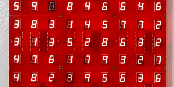
A wooden frame with 64 green LEDs running a Game of Life simulation

Wooden CNC Sculpture Displays Conway’s Game Of Life

Conway’s Game of Life has been the object of fascination for computer hobbyists for decades. Watching the generations tick by is mesmerizing to watch, but programming the data structure and implementing the rules is also a rewarding experience, especially if you’re just getting acquainted with a new computing platform. Just as rewarding can be creating a nice piece of hardware to run the game on, as [SandwichRising] has just done: check out his beautiful wooden Game of Life implementation.

A set of PCBs implementing an 8x8 LED displayThe main part of his Game is a piece of poplar wood that was CNC routed to produce an 8×8 display adorned with neat chain-like shapes. The display consists of standard 5 mm green LEDs, but they’re not the things you see poking out the front of the wooden frame. Instead, what you’re seeing are 64 lenses made out of epoxy. [SandwichRising] first covered the holes with tape, then poured green epoxy into each one and waited for it to harden. He then took off the tape and applied a drop of UV-cured epoxy on top to create a lens.

All the LEDs are mounted on PCB strips that are hooked up to a central bus going to the main ATmega328P  microcontroller sitting on a separate piece of PCB. Whenever the system is powered on, the game is set to a random state determined by noise, after which the simulation begins. On such a small field it’s pretty common for the game to end up in a stable state or a regular oscillation, which is why the ATmega keeps track of the last few dozen states to determine if this has happened, and if so, reset the game to a random state again.

The source code, as well as .STL files for the PCBs and the frame, are available in the project’s GitHub repository. If woodworking isn’t your thing, there’s plenty of other ways to make neat Game of Life displays, such as inside an alarm clock, with lots of LEDS under a coffee table, or even with a giant flip-dot display.

A clock made with LED displays and reflective film

Clever Optics Make Clock’s Digits Float In Space

If you’ve never heard of Aerial Imaging by Retro-Reflection, or AIRR for short, you’re probably not the only one. It’s a technique developed by researchers at Utsunomiya University that uses beam splitters and retroreflective foil to create the illusion of an image floating freely in the air. Hackaday alum [Moritz v. Sivers] has been experimenting with the technique to make — what else — a clock, appropriately called the Floating Display Clock.

The most commonly available retroreflective films are typically used for things like street signs and high-visibility clothing, but also work perfectly fine for homebrew AIRR setups. [Moritz] tried several types and found that one called Oralite Superlens 3000 resulted in the best image quality. He combined it with a sheet of teleprompter glass and mounted both in their appropriate orientation in a black 3D printed enclosure.

An inside view of a clock based on the AIRR projection techniqueThe projected image is generated by a set of 8×8 RGB LED displays, which are driven by a PCA9685 sixteen-channel servo driver board. A Wemos D1 Mini fetches the time from an NTP server and operates the display system, which includes not only the LED panels but also a set of servos that tilt each digit when it changes, giving the clock an added 3D effect that matches nicely with the odd illusion of digits floating in space.

We can imagine it’s pretty hard to capture the end result on video, and the demonstration embedded below probably doesn’t do it justice. But thanks to [Moritz]’s clear step-by-step instructions on his Instructables page, it shouldn’t be too hard to replicate his project and see for yourself what it looks like in real life.

Although this isn’t a hologram, it does look similar to the many display types that are commonly called “holographic”. If you want to make actual holograms, that’s entirely possible, too.

Continue reading “Clever Optics Make Clock’s Digits Float In Space”

PCB Makes 7 Segment Displays

Of course, there’s nothing unusual about using 7-segment displays, especially in a clock. However, [Edison Science Corner] didn’t buy displays. Instead, he fabricated them from a PCB using 0805 LEDs for the segments. You can see the resulting clock project in the video below.

While the idea is good, we might have been tempted to use a pair of LEDs for each segment or used a diffuser to blur the LEDs. The bare look is nice, but it can make reading some numerals slightly confusing.

Continue reading “PCB Makes 7 Segment Displays”

Exploded version of the Cistercian display

Serial Cistercian Digit Module

There’s no doubt that the 7-segment display is a gold standard for displaying lighted digits. But what about a throwback to an older system of displaying numbers — Cistercian? With thirty-one 0805 LEDs, [Josue Alejandro] made a simple module displaying a single Cistercian digit (any from 0-9999).

The first iteration used castellated edges and required a significant number of GPIO, so on the next rev, he switched to a serial-to-parallel converted from Lumissil (IS31FL3726A). A diffuser and spacer were printed from PLA and made for an incredibly snazzy-looking package.

Of course, it couldn’t stop there, and a third revision was made that uses SK6812 Neopixels, allowing full RGB capability. All the design documents, layout files, and incredibly detailed drawings are available on GitHub. What makes this incredibly handy is having a module you can easily add to a project. Perhaps even as a component in an escape room in a box that would allow you to flash multiple numbers. Or perhaps as a stylish clock. We’d even go so far as to challenge someone to create a calculator by combining several of these modules with this keypad.

Quick Tip Improves Seven-Segment LED Visibility

We’re suckers for a nice seven-segment LED display around these parts, and judging by how often they seem to pop up in the projects that come our way, it seems the community is rather fond of them as well. But though they’re cheap, easy to work with, and give off that all important retro vibe, they certainly aren’t perfect. For one thing, their visibility can be pretty poor in some lighting conditions, especially if you’re trying to photograph them for documentation purposes.

The tint film can be cut to size once applied.

If this is a problem you’ve run into recently, [Hugatry] has a simple tip that might save you some aggravation. With a scrap piece of automotive window tint material, it’s easy to cut a custom filter that you can apply directly to the face of the display. As seen in the video, the improvement is quite dramatic. The digits were barely visible before, but with the added contrast provided by the tint, they stand bright and beautiful against the newly darkened background.

[Hugatry] used 5% tint film for this demonstration since it was what he already had on hand, but you might want to experiment with different values depending on the ambient light levels where you’re most likely to be reading the display. The stuff is certainly cheap enough to play around with — a quick check seems to show that for $10 USD you can get enough film to cover a few hundred displays. Which, depending on the project, isn’t nearly as overkill as you might think.

Continue reading “Quick Tip Improves Seven-Segment LED Visibility”

Teardown: VTech Smart Start

Regular readers may be aware that I have a certain affinity for vintage VTech educational toys, especially ones that attempted to visually or even functionally tie in with contemporary computer design. In the late 1980s, when it became obvious the personal computer was here to stay, these devices were seen as an affordable way to give kids and even young teens hands-on time with something that at least somewhat resembled the far more expensive machines their parents were using.

Much Smarter: VTech PreComputer 1000

A perfect example is the PreComputer 1000, released in 1988. Featuring a full QWERTY keyboard and the ability to run BASIC programs, it truly blurred the line between toy and computer. In fact from a technical standpoint it wasn’t far removed from early desktop computers, as it was powered by the same Zilog Z80 CPU found in the TRS-80 Model I.

By comparison, the Smart Start has more in common with a desktop electronic calculator. Even though it was released just two years prior to the PreComputer 1000, you can tell at a glance that it’s a far more simplistic device. That’s due at least in part to the fact that it was aimed at a younger audience, but surely the rapid advancement of computer technology at the time also played a part. Somewhat ironically, VTech did still at least attempt to make the Smart Start look like a desktop computer, complete with the faux disk drive on the front panel.

Of course, looks can be deceiving. While the Smart Start looks decidedly juvenile on the outside, that doesn’t mean there aren’t a few surprising technical discoveries lurking under its beige plastic exterior. There’s only one way to find out.

Continue reading “Teardown: VTech Smart Start”

RGB LED Shutter Shades

[splat238] is back at it again with another cool RGB LED display project. We were contemplating whether or not our readers have had enough of these over the last few weeks, but we’ve learned over the years that you can never have too many LED projects.

Instead of making a cool mask like we’ve covered before, [splat238] decided to trick-out some shutter shades. What’s really cool is he used the PCB itself as the frame, similar to another hack we’ve seen, which we’re sure also made his design process that much more convenient.

[splat238] got his boards pre-assembled since it would be really difficult to solder all those LEDs by hand. There are 76 of them in this design. It’s pretty helpful that he walks the reader through how to get the boards assembled, providing information on reliable fabrication and assembly houses that he’s had good experiences with. Pretty solid information if you don’t already have a go-to one-stop-house or have never designed for assembly before.

The glasses use an ESP8266-based microcontroller since it has plenty of space for storing LED patterns and has the potential benefit of including WiFi control in later revisions. However, we think you’ll be pretty happy with simply toggling through the patterns with a simple pushbutton.

The LEDs use a whopping 2.5 A at maximum and rely on an external power bank, so you’ll probably want to be really careful wearing this over an extended period of time. Maybe consider doing a bit of PWM to help reduce power consumption.

Another cool project [splat238]! Keep them coming. Continue reading “RGB LED Shutter Shades”