As we’ve seen with some recent posts on the subject here at Hackaday, there seems to be a growing schism within the community about the production of PCBs. Part of the community embraces (relatively) cheap professional fabrication, where you send your design off and get a stack of PCBs in the mail a couple weeks later. Others prefer at home methods of creating PCBs, such as using a CNC, laser engraver, or even the traditional toner transfer. These DIY PCBs take some skill and dedication to produce, but the advantage is that you can have the board in hand the same day you design it. But there may be a third option that seems to have slipped through the cracks.
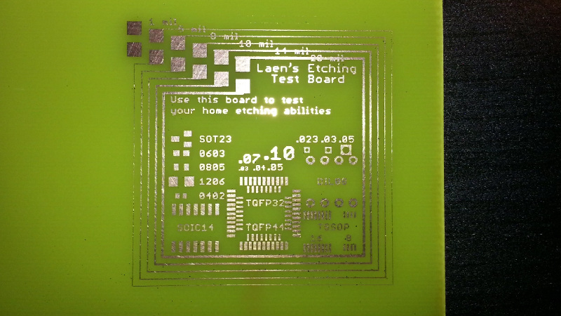
 [Virgil] writes in with a very interesting method of producing professional looking prototype PCBs that doesn’t involve weeks of waiting for the results, nor does it require any complicated techniques or specialized equipment. In this method, a UV printer is used to deposit your mask directly onto the copper clad board, which you then etch with whatever solution you like. Don’t have a UV printer you say? No worries, there’s probably somebody at the mall that does.
As [Virgil] explains, the little kiosks at the mall which offer to personalize items for customers generally use a UV printer which allows them to shoot ink on nearly any material. Instead of asking them to put a logo on the back of your phone, you’ll just be asking them to put the vector file of your mask, which you can bring along on a USB flash drive, onto the bare copper board. They may tell you they can’t guarantee the ink will stick to the bare copper, but just tell them you’re willing to take the risk. It’s one of those situations in which your money will be glad to speak on your behalf.
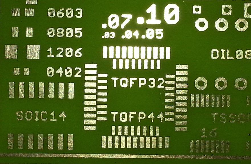
After the UV printer does its thing, the mask might be somewhat fragile. [Virgil] likes to wrap the boards in plastic for the ride home to make sure they don’t get damaged. Then it’s a quick dunk in the etching solution followed by a rinse and some isopropyl alcohol to get the remainder of the UV ink off. The results really do speak for themselves: nice sharp lines with exceptionally little manual work.
We’ve covered some relatively easy ways of quickly producing nice PCBs at home, as long as you don’t mind spending a couple hundred US dollars to get the hardware together. This seems to be the best of both worlds, though it does have the downside of requiring you speak with another human. We’d love to hear from any readers who give this particular method a shot.


This is going to have the same problem that keeps my from ever doing any home PCB manufacture; plated vias are perhaps not impossible, but involve lots of equipment and chemistry that I don’t really want lying around my house.
Yep. The only way I can think of making that less painful is using through-hole components and soldering both sides.
The other way is to make your own vias by the same plating, and then taking a piece of copper wire, shove it in there, solder and dremel.
It all depends how much work you want to do vs buy shit from china and wait.
Back when the world was young, we had the option of “PCB via rivets”.
You’d drill your via holes slightly oversize, then solder in the rivet from both sides.
See http://fab.cba.mit.edu/classes/863.16/doc/tutorials/PCB_Rivets/
PCB rivets are still very much a thing:
https://www.ebay.com/sch/i.html?_nkw=pcb+rivets&_sop=12
I had to buy a bag of 1000 of them for a small project. I still have 990 of them. Wire or leads soldered to matching pads on a double sided board is much easier.
A bare strand of copper wire does look like the easiest option. https://youtu.be/N7Si4N8wbW8?t=52s
I once considered that, but I would not consider the required size of the holes as “slightly oversized”. I would call them huge. I think it was impossible to have a track between two “riveted” IC pins.
But anyway: I have not used THT components for many years.
I use PCB rivets when I have to. They’re nicely dimensioned so that they stick in the hole with minimal fuss when flipping the board over to solder.
Having a hole in the center means that if you buy the big ones (0.8 mm ID, 1 mm OD) you can still insert most components into them. This is key for pinheaders, which are always a PITA to solder the top-side on.
It’s more efficient to strip a long piece of wire, lace it through a bunch of vias, solder them all, then flush cut. The lacing holds the wire in place for soldering, way better than messing around with little bits of wire.
However, the larger problem here is not the soldering of the vias, but the likelihood that a mall kiosk operator is going to get anything resembling top-bottom registration for a double sided board. This technique would be best suited for through-hole, or surface mount with pad for wire jumpers when your single-sided routing has hit a wall.
Is registration that big a deal? Drill a couple of largish-diameter holes on opposite corners of the board and do it by eye. Or 3D print a cradle for the board to sit in and fix it to the printer with double-sided tape.
In the context of the article, we’re talking about handing your PCB to someone in a mall kiosk. So I’d say that registration is a real concern, considering that if you have any process more fiddly than “insert item, press button” you now have to train this person to make your PCBs.
I use 0.5mm drill and make a via rivet from Ethernet wire about 2mm long on a 1.6mm PCB. https://youtu.be/eRo7yQSXF4Y,
Also I used the 3D printed base to locate both sides of the PCB. needed to tram my 3d printer with threaded rod diagonally within 1mm to get repeatable +/-0.25mm accuracy across the 16x14cm double sided PCB.
Drill, paint, engrave, etch, use engrave to expose solder mask areas, install copper rivets, solder components, sacrifice a large transistor to the electronic Gods, finally plug in power and watch your creation come to life.
Wire vias are a few extra steps, but it’s not really that difficult. Dremel hardware is pretty cheap, got a dremel and drill press for it, and a table router/cutter attachment as well as PCB drill bits for under $100.
Drill the holes, stuff them with copper wire, and add solder. After getting the PCBs from the printer, the etching, cleaning, drilling, and vias should take about 3 hours or less. And it should be pretty cheap – except for your time. Sometimes the speed of iteration and rapid development/prototyping makes it worth your time when on a budget.
If I had the $5K for a UV printer, i’d have one on my desk right now cranking out PCBs. Genius idea, great find. I want to try it.
I used a copper nail that I cut. A bit longer than the board thickness. Then I would hammer it in with a small hammer on a flat hard surface. The copper would cold weld / fuse and I could get almost invisible vias
Yes I did that in the old days. But there were always some places which were nearly inaccessible, at least you had to plan very carefully, in which sequence you populate the ICs. If you wanted to use sockets, it was even more difficult. But I used them only for expensive ICs like processors or EEPROMs.
For prototypes I just put header pins and solder them in place on both sides. They’re messier than nice plated vias but they’re easy and they work.
One technique I’ve used for this is to use conductive ink. I place an absorbent material on one side (like a paper towel) to help draw the ink through, then dab ink into the via hole on the other side. Once it is dried, dampen a rag lightly with acetone and clean up the surface.
Interesting idea.
Conductive ink or past was also used in some commercial products. But the reliability was not great.
single side, zero ohm resistors as bridges + a lot of routing practice :)
Yep that is my reasoning too. This is an interesting idea for that reason and some Panda Express samples on the way :)
Completely true, that’s the same reason, I am not really interested in milling the traces.
I would not have any problems having the chemicals lying in my house. They are not that toxic. But I know they have a bad shelf life. So when you want to make the occasional PCB, they are probably already spoiled.
Re: shelf life. Not true! I used the same batch of copper-chloride-based etchant for five or six years before I moved internationally and had to dispose of it. I use the same batch now that I made in 2011. Hundreds of home-made PCBs over (holy cow!) twelve years. The chemistry isn’t the issue.
(Granted, I top up with additional acid and oxygen, but that’s it for upkeep.)
How do you align the traces if you are doing 2 sided PCBs?
Very carefully.
Some will drill a couple of “fiduciary” holes before etching to line up the masks.
Or make you via areas large enough to compensate for slop.
It’s fiducial holes, fiduciary is something else..
I engrave my boards – https://hackaday.io/project/160688-turning-3d-printer-into-engraver . Fast, can get 1mil, no need for UV, no side scattering. Maybe not the best way, but works saving some steps.
Interesting. I had previously thought about putting an engraving tool on my 3d printer, but never thought about using it for PCB production.
Double sided boards, plated vias… ok so those things are difficult.
So what?
What if you can make some of your boards yourself this way. But.. more complicated designs still require waiting for China. How is that still not an improvement compared to always waiting?
Here’s the trick. Design your boards to be as close to single sided as possible and use via sizes that are large enough to double as through-hole pads.
If you manage to make it completely one-sided then awesome, you are done!
If there are just a handful of traces on the bottom then that’s no big deal. Just etch the top half as a single sided board. Then use those big oversized vias I mentioned as the connection points for jumper wires.
If there are too many bottom-sided traces and you are starting to design a jumper-wire rats nest that’s ok. Nobody says (well I don’t anyway) that EVERY board you make needs to be home etched. Go back to your usual double-sided design style. Send that puppy away and go find something else to do for the next month and a half while you wait. Maybe go talk to some girls (or boys, whatever you prefer).
I guess it depends where you live in the world. I can get boards done on a two-day turnaround for around €100 if I’m in a hurry. If I’m not in a hurry, Chinese fabs will do two day turnaround for $5 plus about $15 for shipping that takes just over a week to get here (these numbers from my last real order).
It’s not the same as making it yourself on the same day, but it’s not a month and a half, either.
Yes, it really depends on where you live. Here, those $20 would represent much more than reasonable to spend in a prototype, and would take more than a month to arrive. With the added possibility of being stopped at customs then being charged something more ( probably about $5 in that kind of order ) to be released. And in case we decide to abandon it in Customs, well, the chinese fab will not reimburse our $20 .
I usually design simple boards with 1 side of signals, and the other side a solid ground plane. It’s a good practice anyway from EMC point of view, and makes manufacturing at home easy. Soldering thin wire for the vias is not too annoying, though I’ve had some trouble with the vias not being 100% reliable over time.
What would be the cost of just buying a UV printer and ink?
On Ebay, you can find small ones (for printing phone cases) starting at about $2000. There also seems to be a DIY community that has converted some regular ink jet printers into flatbed UV printers.
This was my thought. I wonder when these hit the used market cheap?
People have also used a wax-based printing tech as etch resist. Those printers may be more easily/affordably available, and are probably a good solution if you’re making a lot of boards.
But it’s really great to have a solution like this where you just want one board made (maybe per month?) and it’s easier to let someone else own and maintain the printer.
I’m not really sure why the UV printers are so expensive? What makes them so special that requires the cost to be so high?
Or, just do 2 single sided boards and accomplish the double sided registration by aligning the standalone layers with the side-to-side jumper wires.
Who’s going to be the first to used laser-sintered copper to construct an air-dielectric circuit? Guess some kind of ceramic supports would be needed. but I always thought boards – particularly high layer count ones – with burnt components were so cool when the epoxy burns away and traces are just floating in space.
Interesting, now that Ben Krasnow has shown how to clad a plastic with copper, we can increase the thickness by an electroless process, then dissolve the plastic.
Another thought about working around the lack of plated vias- with all the little Bluetooth modules that use plated pcb edges for contacts to mount as a sub-assembly, take that concept to make “component vias” that you can design in as passives and solder in place. SMT equivalent to dozens of jumper wires. Keep a stock handy but mass produce in China/etc.
I think I do not really understand you. 0 Ohm SMD jumpers exist in all sizes and the pcb rivets as vias exist.
Same concept, except lots of contacts and longer spans. Mass produce some useful sizes and keep in inventory, drop them in like any other component, and reflow-friendly. PCB rivets sound like a LOT of work.
Some people have success using a laser printer on slick magazine pages and soak paper with acetone to transfer toner from paper to copper. https://youtu.be/cVhSCEPINpM
The transfer is usually done with a flatiron or a modified laminatpr (MOOORE POWER) and then the paper is removed with acetone.
Works ok once you get the hang of it. It’s even great for silkscreen but needs a clearcoat to be scratch resistant
Weird, this used to be the main method just yesterday.
Any glossy paper would do. Print on it, fold in half and align the holes against bright light. Glue from the side opposite of the fold to avoid misalignment later. Insert cleaned pcb (NH4OH works great for making toner stick better), then carefully push into the laminator. It should bite gently but firmly and if it does not jam your paper, after some soaking in warm water you get your pcb with resist applied. Takes some 10 minutes, but maybe several attempts before you dial in the right temperature etc.
Above link shows that heat is NOT needed. If you wanted to, for double-sided pcb, you could probably drill 3 registration holes in the board prior to doing anything else by using a plain paper print as a guide. Then clean the board with 000 steel wool and wipe oils off with paper towel and acetone. Register laser-printed slick paper onto copper, tape in place, soak with acetone, apply pressure by rubbing with fingers (or use a roller), then peel paper off board leaving toner adhered to copper. Board is ready for etchant bath. Very fast, simple, and inexpensive for a few boards.
I see, thanks for verbalising it. Sounds interesting, though a bit ringy in the ears due to acetone vapours.
I played around with the acetone method for a day, and was never able to get results as consistent as with heat/pressure transfer, where I get results that can discriminate between 600 DPI and 1200 DPI.
The nice thing about (lower) heat and a ton of pressure is that with practice you can keep the toner plastic — sticky but not squishy like when it melts.
https://hackaday.com/2016/09/12/take-your-pcbs-from-good-to-great-toner-transfer/
With acetone, how do you keep the toner from melting/squishing?
what is the radio rat fg” the board is shown in the video
Hmmm.. When I saw the headline my mind went to SLA printers as being UV printers.
After reading the story, I’m now thinking that you could potentially get a similar result from an SLA printer? Clean the board, put it face-down in the bath and expose the tracks as an etch resist?
I’m sure an SLA printer could be used for exposing etch resist, as could my Anycubic Photon DLP printer. Just like this technique though – UV exposure is the easy bit. A transparency and a UV light source has always worked well on the past.
Making a good transparency with a laser printer used to be a bit fiddly. They print well for reading or slides, but for PCB stuff, the fills tend to be spongy, not perfectly opaque.
I used to have some highly aromatic solvent in a spray bottle that you could very gently apply to a transparency, and with luck it would not create stains and make it optically more dense.
Inkjet works much better for transparencies – especially T shirt printing mode on my Canon MG-5250. I think everyone seems to use a laser printer as they get confused with toner transfer.
Owning an inkjet is (at least used to be) a bit taxing because unless you print every now and then it tends to get clogged. A laser printer is something you stash away on a shelf for a few years, then take it and print again like nothing happened.
That is true. I suspect most of the ink my printer users goes towards “nozzle cleaning”. It does print good transparencies though.
LPKF’s PCB prototype making machines drill vias then squeegee a conductive paste through them.
Until someone makes this a hobbyist reality, only the simplest of designs make sense to DIY.
I made a PCB when I was a kid. The challenge wasn’t the art. The challenge was drilling the holes precisely enough even for a DIP.
I respect those who do their own PCBs, but OSHPark is only $5/sq” and a week for 3 boards with two sides, plated vias, soldermask and silkscreen.