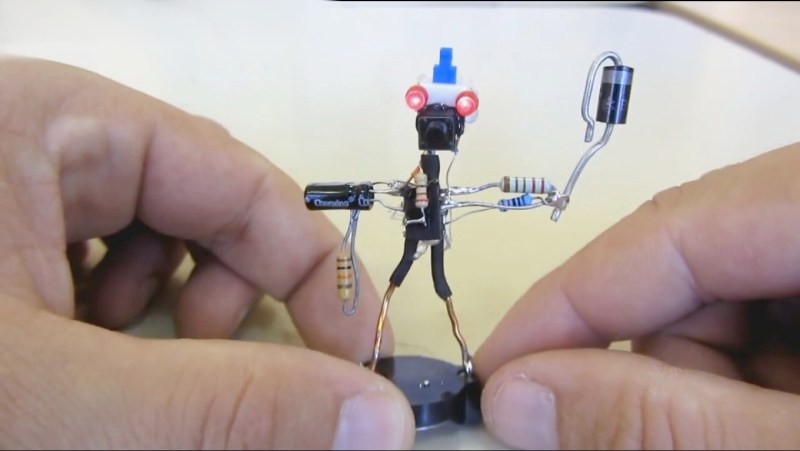
A running joke we see in the comments by Hackaday readers whenever a project includes an Arduino or Raspberry Pi that seems like overkill is to proclaim that “I could have done it with a 555 timer!” That’s especially the case if the project amounts to a blinking light or anything which oscillates. Well [Danko Bertović] has made a whole robot out of a 555 timer circuit in his latest Volos Projects video.
Okay, it’s really a dead bug circuit in the shape of a robot but it does have blinking lights. We also like how the base is the battery, though some unevenness under it seems to make the whole thing a bit unstable as you can see in the video below. There are also a few parts which are cosmetic only. But it’s cute, it’s a 555 timer circuit, and it’s shaped like a robot. That all makes it a win.
We do wonder how it can be taken further. After all, a walk cycle is a sort of oscillation so the 555 timer circuit could run some servo motors or at least some piezoelectric feet. Ideas anyone?
On the other hand, if you’re looking for a dead bug circuit which belongs in a fine arts museum then you need look no further than The Clock.


gorgeous
It’s in an unstable configuration
I see what you did there!
It’s an astable circuit!
3 x 555 should be enough o let this robot walk https://www.youtube.com/watch?v=DWSbFfW3lC4
There is a huge branding opportunity for HAD to put out shirts & swag with ““I could have done it with a 555 timer!” and the Jolly Wrencher©.
+1
“…and then send one to the RPi group…
I’d buy that… price permitting…
555s? I could have done it with just a pair of transistors!
https://www.electronics-tutorials.ws/waveforms/astable.html
carved from wood!
You made me laugh. Thanks! :D
Or maybe a unijunction transistor.
The 555 took away many jobs from the UJT, so they are much less common now.
Two relays might work, but that’s going back to complexity.
Michael
You would only need one relay to make an oscillator. Add a cap to slow it down.
It is less complex than 555.
http://everycircuit.com/circuit/5647020571754496/relay-oscillator
“I could have done it with a 555 timer!”
oh wait…
You already made that preemptive strike…
B^)
When I was in high school (80s), I build a simple obstacle-avoidance robot entirely controlled by 555 timers, just to see what could be done.
The robot had two separate motors with relay (!) directional bridges on them for reversing the motors. Each motor drove a large wheel, one on each side, and there was a roller-ball caster in the front for balance. On the front and rear of the robot were strategically-placed microswitches with levers ending in a “cat whisker”, one on the left and one on the right. The robot started out driving both motors forward. When its forward cat whisker hit an obstacle, the microswitch triggered a monostable 555 that reversed the motors for a short time, such that the robot rotated away from the obstruction. There were some transistor-based logic to establish a “priority” for which direction to rotate. For simple obstructions such as the walls of a room, it worked.
I don’t think I have any pictures of it tho…
Same idea, different species…
https://www.instructables.com/id/Dead-Bug-Doggie/
Odd. When I see a 555 project I think to myself.. “Why not just use a microcontroller?”. SM8, ATTINY and PIC10s are the same price.
Now when I see both a Rasbery Pi and a 555, I don’t have the same thought. Instead, I recognize an electronic hobbyist and move on.
Odd. When I see a Raspberry Pi in a project, I move on.
I could do it Lm3909. Not a a real robot. Need a 555/6/8 for that and maybe sone relays but servos actually cheaper. snicker
you could have done this using two BJTs and a couple of passives. You can’t beat a simple astable multivibrator in an application like this.
e.g.
https://www.youtube.com/watch?v=VadOCNimVrM
you can also chain them
https://www.eleccircuit.com/three-led-flasher-by-3-transistor-astable-multivibrator/
https://www.youtube.com/watch?v=q1MrKSHh-5Y