Circuit Sculpture Hack Chat

Join us on Wednesday, November 6 at noon Pacific for the Circuit Sculpture Hack Chat with Mohit Bhoite!

For all the effort engineers put into electronic design, very few people ever get to appreciate it. All the hard work that goes into laying out a good PCB and carefully selecting just the right components is hidden the moment the board is slipped into an enclosure, only to be interacted with again through a user interface that gets all the credit for the look and feel of the product.

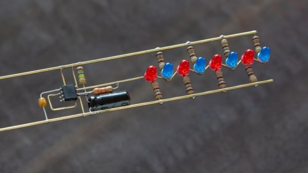
And yet there are some who design circuits purely as works of art. They may do something interesting or useful, but function is generally secondary to form for these circuit sculptors. Often consisting of skeletons of brass wire bent at precise angles to form intricate structures, circuit sculptures are the zen garden of electronic design: they’re where the designer turns to quiet the madness of making deadlines and meeting specs by focusing on the beauty of components themselves and putting them on display for all to enjoy.

By day, our host Mohit designs and builds hardware at Particle. By night, however, the wires and pliers come out, and he makes circuit sculptures that come alive. Check out his portfolio; you won’t be disappointed. This Hack Chat will be your chance to find out everything that goes into making these sculptures. Find out where Mohit gets his inspiration, learn his secrets for such precise, satisfyingly crisp wire-bending, and see what it takes to turn silicon into art.

join-hack-chat

Our Hack Chats are live community events in the Hackaday.io Hack Chat group messaging. This week we’ll be sitting down on Wednesday, November 6 at 12:00 PM Pacific time. If time zones have got you down, we have a handy time zone converter.

Click that speech bubble to the right, and you’ll be taken directly to the Hack Chat group on Hackaday.io. You don’t have to wait until Wednesday; join whenever you want and you can see what the community is talking about. Continue reading “Circuit Sculpture Hack Chat”

DIY Clapper Lets You Pick Your Components

One thing that always means the end of the year is close is the reappearance of TV ads for “The Clapper.” After all, who needs home automation when you can clap on and clap off? While we’re partial to our usual home automation solutions, [Utsource123] shows us that building a clapper can be a fun and easy project using several similar circuits. One with a few transistors and another one with a 555 because, after all, what can’t a 555 do?

Of course, these circuits usually have a microphone. We were trying to think of how you could make a sound-sensitive element out of common parts. After all, you don’t care about the fidelity of the microphone pickup, just that it hears a loud noise. The circuits are about what you’d expect. The transistor version uses one to amplify the microphone and another to switch on the LED. You’d need a bit more to trigger a relay. The 555 uses an even simpler preamp transistor as a trigger.

While we aren’t bowled over with the idea of a clapper, we imagine these circuits aren’t far removed from the ones you buy in stores. For about $16 you also get enough switching to handle a simple AC load, though. Maybe Alexa and Google should allow making clapping a wake up word?

This is sure simpler than the last clapper clone we saw. Then there’s the deluxe DIY version.

Dead Bug Arduino Is Lively And Shield-Compatible

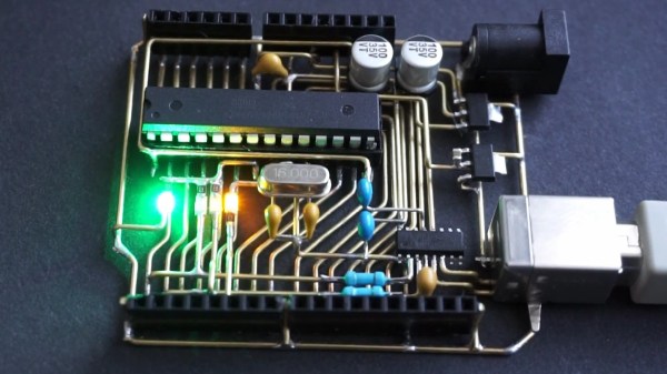
Microcontroller demo boards such as the Arduino UNO are ubiquitous on Hackaday as the brains of many a project which inevitably does something impressive or unusual. Sometime someone builds a particularly tiny demo board, or an impressively large one. In the case of the board featured here, the Arduino is a gorgeous labor of love which can’t really be called a board since there is no PCB. Instead of the traditional fiberglass, [Jiří Praus] formed brass bars into the circuitry and held it together with solder.

This kind of dedication to a project leaves an impression. His notes show he saw the barest way to operate an ATMega328, built it, tested, and moved on to the power supply to make it self-sustaining, then onto the communication circuit, and finally the lights. The video below shows a fully-functional Arduino happily running the blink program. He plans to encase the brass portion in resin to toughen it up and presumably keep every bump from causing a short circuit. The components are in the same position due to a custom jig which means a standard shield will fit right into place.

The Arduino started far less flashy yet nearly as fragile, and it has grown. And shrunk.

Continue reading “Dead Bug Arduino Is Lively And Shield-Compatible”

Help For High-Frequency Hobbyists

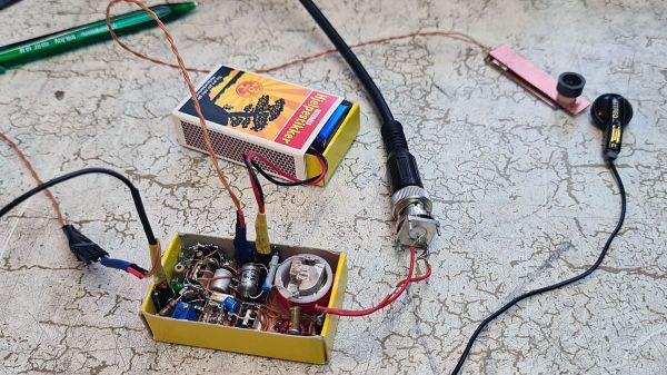
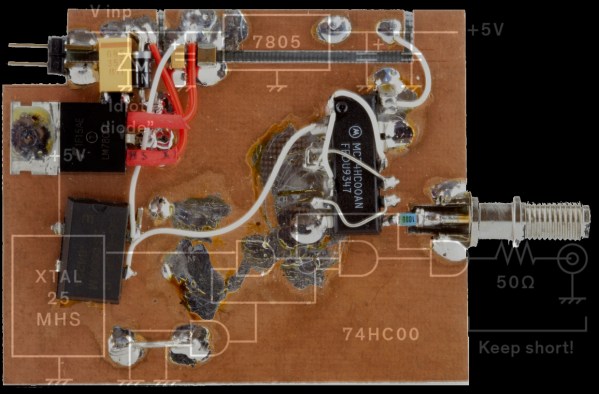
Dead-bug circuit building is not a pretty affair, but hey, function over form. We usually make them because we don’t have a copper circuit board available or the duty of making one at home is not worth the efforts and chemical stains.

[Robert Melville and Alaina G. Levine] bring to light a compromise for high-frequency prototypes which uses the typical FR4 blank circuit board, but no etching chemicals. The problem with high-frequency radio is that building a circuit on a breadboard will not work because there is too much added inductance and capacitance from the wiring that will wreak havoc on the whole circuit. The solution is not new, build your radio module on a circuit board by constructing “lands” over a conductive ground plane, where components can be isolated on the same unetched board.

All right, sometimes dead-bug circuits capture an aesthetic all their own, especially when they look like this and they do allow for a darned small package for one-off designs.

Minimal Blinky Project Makes The Chip The Circuit Board

We’ve got a thing for projects that have no real practical value but instead seek to answer a simple yet fundamental question: I wonder if I can do that? This dead-bug style 555 blinky light is one of those projects, undertaken just to see how small a circuit can be. Pretty small, as it turns out, and we bet it can get even smaller.

[Danko]’s minimal circuit is about as small as possible for the DIP version of the venerable 555 chip. The BOM is stripped to the bone: just the chip, three resistors, a capacitor, and an LED. All the discrete components are SMDs in 0805. The chip’s leads are bent around the package to form connections, and the SMDs bridge those “traces” to complete the circuit. [Danko] shows the build in step-by-step detail in the video below. There’s some fairly fine work here, but we can’t help wondering just how far down the scale this could be pushed. We know someone’s made a smaller blinky using a tiny microcontroller, but we’d love to see this tried with the BGA version of the chip which is only 1.4 mm on a side.

Cheers to [Danko] for trying this out and having some fun with an old chip. He seems to have a bit of a thing for the 555; check out this cute robot sculpture that’s built around the chip.

Continue reading “Minimal Blinky Project Makes The Chip The Circuit Board”

555 timer circuit robot

555 Timer Robots Will Rule The World

A running joke we see in the comments by Hackaday readers whenever a project includes an Arduino or Raspberry Pi that seems like overkill is to proclaim that “I could have done it with a 555 timer!” That’s especially the case if the project amounts to a blinking light or anything which oscillates. Well [Danko Bertović] has made a whole robot out of a 555 timer circuit in his latest Volos Projects video.

Okay, it’s really a dead bug circuit in the shape of a robot but it does have blinking lights. We also like how the base is the battery, though some unevenness under it seems to make the whole thing a bit unstable as you can see in the video below. There are also a few parts which are cosmetic only. But it’s cute, it’s a 555 timer circuit, and it’s shaped like a robot. That all makes it a win.

We do wonder how it can be taken further. After all, a walk cycle is a sort of oscillation so the 555 timer circuit could run some servo motors or at least some piezoelectric feet. Ideas anyone?

On the other hand, if you’re looking for a dead bug circuit which belongs in a fine arts museum then you need look no further than The Clock.

Continue reading “555 Timer Robots Will Rule The World”

Vintage Silverstone Bluetooth speaker

Vintage Silvertone Cabinet Gets Bluetooth Treatment

This Bluetooth speaker is full of delightful surprises. The outer shell is an antique radio cabinet, but its practically empty interior is a combination of Dead Bug circuitry and modern BT receiver.

[PJ Allen] found the BT receiver on Groupon and decided to whip up amplifier and threshold detector circuits using only parts he already had in order to make this vintage-looking Bluetooth speaker. The cabinet is from a Silvertone Model 1955 circa 1936. Don’t worry, no antiques were harmed in the making of this hack, the cabinet was empty when he bought it.

LM4871 based amplifiers

The amplifiers, one per speaker, began life as a circuit from TI’s LM4871  datasheet. Some of the departures came about because he didn’t have the exact component values, even paralleling capacitors to get in the right range. The finished board is a delightful mix of “Dead Bug” and quasi-Manhattan style construction, “quasi” because he carved up the ground plane instead of laying pads on top of it.

Look at the front of the cabinet and you’ll see a rectangular display. Watch the video below and you’ll see that it throbs in time to the music. To do that he came up with a threshold detector circuit which started out based on a circuit from a  Sharp/Optonica cassette tape deck, but to which he made improvements.

Not all cabinets come empty though. Check out this post by our own [Gregory L. Charvat] about restoring these wonderful old radios.

Continue reading “Vintage Silvertone Cabinet Gets Bluetooth Treatment”