When working on a project that needs to send data from place to place the distances involved often dictate the method of sending. Are the two chunks of the system on one PCB? A “vanilla” communication protocol like i2c or SPI is probably fine unless there are more exotic requirements. Are the two components mechanically separated? Do they move around? Do they need to be far apart? Reconfigurable? A trendy answer might be to add Bluetooth Low Energy or WiFi to everything but that obviously comes with a set of costs and drawbacks. What about just using really long wires? [Pat] needed to connect six boards to a central node over distances of several feet and learned a few tricks in the process.
 When connecting two nodes together via wires it seems like choosing a protocol and plugging everything in is all that’s required, right? [Pat]’s first set of learnings is about the problems that happen when you try that. It turns out that “long wire” is another way to spell “antenna”, and if you happen to be unlucky enough to catch a passing wave that particular property can fry pins on your micro.
Plus it turns out wires have resistance proportional to their length (who would have though!) so those sharp square clock signals turn into gently rolling hills. Even getting to the point where those rolling hills travel between the two devices requires driving drive the lines harder than the average micro can manage. The solution? A differential pair. Check out the post to learn about one way to do that.
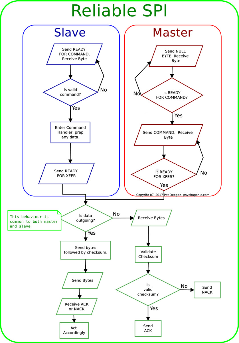
It looks like [Pat] needed to add USB to this witches brew and ended up choosing a pretty strange part from FTDI, the Vinculum II. The VNC2 seemed like a great choice with a rich set of peripherals and two configurable USB Host/Peripheral controllers but it turned out to be a nightmare for development. [Pat]’s writeup of the related troubles is a fun and familiar read. The workaround for an incredible set of undocumented bad behaviors in the SPI peripheral was to add a thick layer of reliability related messaging on top of the physical communication layer. Check out the state machine for a taste, and the original post for a detailed description.


oh men, this sounds like somebody had a lot of fun…
Differential signals are your friend
I’d have thought this would have been a good case for something like RS485 if overall, speed wasn’t an issue.
He could have even used a simple variant of CAN – costs very slightly more for a small micro and a CAN transciever at each end but it would have permitted daisy chaining the devices into a bus with proper error detection and wire access arbitration between the nodes. And the PC interface would have been much simpler, not requiring one connector per sensor node.
Also the Vinculum bugs and problems are well known – it is a crappy part with a reputation to match.
But where is the fun in doing a bit of research before starting soldering, right? Reinventing the wheel (and poorly at that) is the way to go …
Oh and the best part – if you go to psychogenic.com (the address silkscreened on the boards), you will find this:
https://psychogenic.com/project/psycan-modules-can-bus-made-easy/
So they have a product using CAN for exactly the same purpose already. I really don’t get the reason why this hacked up mess was conceived.
I do… it’s called “inventing the wheel” or “time for a real standard”. But in a lot of cases it is mainly ignorance, not knowing that and why some solutions (to your problem) already exist. In some cases it is a matter of thinking that you can make something better/cheaper/etc. then the things that already exist.
Though in most cases, the problem itself is underestimated and tiny fixes are added until there is no way back to say you approached the problem the wrong way. Or there is no way back due to time limits and additional costs.
Thankfully, by posting this “project” here it is sort of learning material for others.
Which brings me to the point where I would like to state that it is complete bullocks that the article opened with the statements:
“… “antenna”, and if you happen to be unlucky enough to catch a passing wave that particular property can fry pins on your micro.” if radio signals are that strong, you are most likely sitting on an antenna. My experience is that if you fry something you most likely fried it because of potential differences in the power supply (crappy badly filtered power supply) on one or both of the two ends. Or static electricty (lightning hitting your cable).
“wires have resistance proportional to their length… so those sharp square clock signals turn into gently rolling hills” ehmm, resistance is true, but if resistance is really the problem, you are most likely are sending a lot of current through it… and if you don’t… then perhaps you should, because long cables have add a lot of capacitance to your circuit, and if you are not able to charge that… ravines become hills. So to make a long story short, know you circuit before you judge. The resistance of wires is mostly an issue when using the wires for the transmission of power (voltage drop). The capacitance of the wire is mostly an issue because your output driver isn’t able to charge the capacitance fast enough. Use push pull drivers instead of open collector or go differential for many other reasons.
“Though in most cases, the problem itself is underestimated and tiny fixes are added until there is no way back to say you approached the problem the wrong way. Or there is no way back due to time limits and additional costs.”
At least software is more forgiving when taking that approach, except for the time thing.
resistance (capacitance/inductance) proportional to their length (who would have though!) so those sharp square clock signals turn into gently rolling hills
I used to be a developer at FTDI. Worked on some of the FT900 stuff. All I can say is: I feel your pain
Friends don’t let friends use FTDI. Ever.
“The solution? A differential pair. ”
The solution to rolling hills instead of crisp pulses isn’t a differential pair, it’s understanding the characteristic impedance of your path, including conductor, source and destination impedances, and designing outputs and inputs to manage that.
A good differential output driver also happens to help keep the signal crisp because it is intended for driving long lines… but the main contribution of having a “differential” signal path (two i/o circuits in anti-phase) is to cancel out common-mode interference.
Yep. All true, but incomplete. A diff setup also has Schmidt trigger, or hysteresis in the receiver to square things back up again. Impedance matching the line also helps prevent reflections which can cause errors if 2x the transit time down your wire is long enough to be resolved at the receiver end as a separate transition.
There are cases where even a diff pair isn’t good enough. I use a lot of uP’s in conjunction with data aq on my physics stuff, which now and then might have a high current (kilo-amps) arc at 50kv, which will fry even differential stuff if the wires are too close. “Sitting on the transmit antenna” is unavoidable as the data aq has to happen where the data is.
One winds up shielding both ends (HV source wiring and low level data) as well, and paying careful attention to magnetic coupling and ground loops when billion watt pulses are in the mix. For some cases I’m stuck with putting a lot into a Faraday box, and using fiber optics (ethernet) to galvanic-ally isolate the data aq stuff from the recording database machine. Some expensive smoke can result otherwise, along with the loss of data (which is usually the most interesting just before that!).
And of course, some kind of error detection and re-transmit layer is always a good thing…
This makes what seems conceptually trivial into something that can be fairly hard to get right…no one thing is killer, but they have to all be right for the system to fly.
In my experience, with I2C and SPI, capacitive coupling between wires becomes a problem long before the edges are rounded. In fact, adding a series resistor can help it work longer distances by smoothing the corners.
The problem is that the clock line is edge-sensitive, so a reflected pulse from the far end of the line or capacitively coupled change from the data line can cause a spurious edge. And a single extra clock pulse will mess up the whole transfer. And slowing down the bitrate won’t help, like it would with rounded edges, because the problem is the sharpness of the edges causing crosstalk.
I found a scope picture of some SPI traffic. This is just a one meter line, with a slip ring in between. The slip ring had a surprising amount of capacitive coupling. In this image, yellow line is SCK and purple line is MISO. Master is raising the SCK, which has a rise time of about 200ns, which would be fine for the 1MHz bitrate. But when slave detects the rising edge, it very quickly pulls MISO down, which causes a pulse on SCK, which causes it to detect a second clock pulse and MISO changes to next bit too early. Adding a series resistor on MISO helped some, but it is still a quite problematic setup.
https://jpa.kapsi.fi/stuff/pix/tek00000.png