Dead-bug circuit building is not a pretty affair, but hey, function over form. We usually make them because we don’t have a copper circuit board available or the duty of making one at home is not worth the efforts and chemical stains.
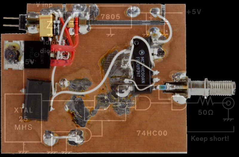
[Robert Melville and Alaina G. Levine] bring to light a compromise for high-frequency prototypes which uses the typical FR4 blank circuit board, but no etching chemicals. The problem with high-frequency radio is that building a circuit on a breadboard will not work because there is too much added inductance and capacitance from the wiring that will wreak havoc on the whole circuit. The solution is not new, build your radio module on a circuit board by constructing “lands” over a conductive ground plane, where components can be isolated on the same unetched board.
All right, sometimes dead-bug circuits capture an aesthetic all their own, especially when they look like this and they do allow for a darned small package for one-off designs.


I would think a 74AC00 with its faster edge rates would work better in this application. Or even one of the new-fangled families like 74LVC00.
74LVC is more trouble than its worth because its rise/fall time is so fast that you’ll need serial termination if the output trace is longer than 1/2″. 74AC has a slower rise/fall time and you can easily get away with 2-3″ of wire.
BTW for this however, the series termination is close, so the LVC should be okay, but it only comes in SMT packages. Not a big deal, but it require a bit better soldering skill than shown.
I’ve also found that with a 5v Vcc, HC and AC logic will tolerate an output briefly shorted to ground but LVC logic fries. The series terminator will help. I was usually paralleling 4-5 gates to make a fast 50-ohm digital signal driver that could tolerate parallel termination on 2 or more end points.
in RF, faster circuitry is not necessarily better…faster rise time then you need = more harmonics that you (usually…) need
OTOH, I’ve used high-speed logic circuits in RF for precisely that reason. They’re cheap and easy to use, and if you’re good at both designing, implementing, and tweaking RC filters, you can use the (odd) harmonics of those nice sharp square waves to obtain frequencies that are a pain to produce otherwise.
I used to first workout my dead-bug SMT designs with scaled-up, plan view paper models of parts, each cut out of the sticky part of a Post It note. With a little jiggery-pokery, you could come up with some very compact, and multi-layered part ‘brick’ designs, some mounted to Xacto knife ‘etched’ blob-board PCB substrates, and all squeezed into things like tiny aluminium cans recycled from ‘popped’ electrolytic capacitors. – Seems an unnecessarily fiddly affair, but I built a low noise satellite dish microphone preamp good enough to listen in on…well, I’d better not go into that one too far.
I’d love to see pictures of the SMT dead bug gadget inside an old capacitor can, that sounds amazing. Think of the sneaky devices you could hide like that!
Thanks for the interest tgt,
No clue how to post images, and no HTTPS, but try these safe links:
http://members.iinet.net.au/~vanluynm/Images/1.JPG
http://members.iinet.net.au/~vanluynm/Images/2.JPG
http://members.iinet.net.au/~vanluynm/Images/3.JPG
HTH,
T.
Damn that’s nice work.
Indeed. Worth of it’s own HaD article.
The “Hidden Gems” series.
Such lovely comments.
Yep, there are 3 x SOT-23 transistors buried in that lot. From way back in the day when 1206 passive parts were the ‘norm’ for SMT electronics.
T.
Really nice! You ever write this up?
If you don’t have a way to host it yourself (and even if you do!): Hackaday.io. (Quickstart)
There are many variations on these techniques. For some more, see the PDFs in the bottom section “Avoiding Solderless Breadboards” of http://bristol.hackspace.org.uk/wiki/doku.php?id=pcb
The last of the three has examples of RF equipment.
Resurrecting? Lots of people still do this. I keep cutoffs from home made pcbs, add some supaglue… Done. :-)
Dead bug? Ha!. Did a +43dbm output amplifier at 220 MHZ. X-Acto cut away copper on pcb, hand wound coils. Only problem was using CM03 capacitors. They unsoldered themselves. Change caps to CM06 and adjust for slight inductance changes (spread or compressed coils) and it worked. Funny thing is that it worked better than did the production version.
If you’ve actually tuned the thing, then there’s no wonder it worked better then the factory made one…they can’t take the time to do it near perfect ;-)
Back in Army Radio school, one of the instructors told us of the time their vehicular radio (standard 40 Watt output)
was tweaked to 120 Watts out.
How to increase TX power at HF frequency, do you have to add booster ??
For those doing a lot of HF work, there’s a way of prototyping that’s often better than ‘dead bug on FR4’. Some makers of prototyping supplies make boards that have component holes on 0.1″ centres, with a pad-per-hole configuration on the bottom, and a ground plane on the top that’s perforated to allow a bit of clearance around the holes.
At a former job we had our own versions of these made by our PCB maker. I still have dozens left over that I use for personal projects. They feature square pads on the bottom, allowing both for easy solder bridging to create traces, and for soldering some types of SM components. Ground connections can be made using a wire from bottom to top, but with most leaded components I simply solder-bridged the leads directly to the top copper layer. I successfully prototyped countless circuits this way, including active RF circuits, (FSK data transmitters and receivers), at frequencies up to 200 MHz, and passive circuits, (custom power-injecting signal splitters for CATV networks), at up to 800 MHz. The latter required maintaining decent wide-band impedance matching at 75 ohms, and I had no problem achieving that with these boards. I’ve also made RF LC filters, as well as various audio circuits, using these boards. They are way more convenient than dead-bug construction, they allow for dead-bug techniques when necessary, and the ground plane works much, much better than you might think by looking at all the holes in it.
If you’re doing a lot of RF prototyping, or even if you’re working with those (increasingly rare) through-hole semis and passives, I recommend looking into this style of prototype board.