Logic probes are simple but handy tools that can be had for a couple of bucks. They may not be the sexiest pieces of test gear, nor the most versatile, but they have their place, and building your own logic probe is a great way to understand the tool’s strength and weaknesses.
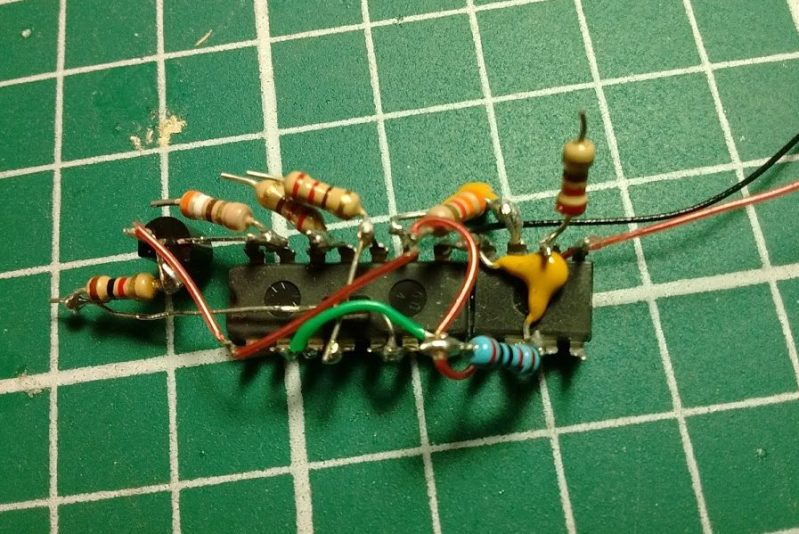
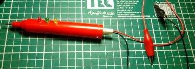
[Jxnblk]’s take on the logic probe is based on a circuit by [Tony van Roon]. The design hearkens back to a simpler time and is based on components that would have been easy to pick up at any Radio Shack once upon a time. The logic section is centered on the venerable 7400 quad 2-input NAND gate in the classic 14-pin DIP format. The gates light separate LEDs for high and low logic levels, and a 555 timer chip in a one-shot configuration acts as a pulse stretcher to catch transients. The DIP packages lend themselves to quick and dirty “dead bug” construction, and the whole thing fits nicely into a discarded marking pen.
It’s a simple build and a nice form factor for a useful tool, but for an even slimmer package like an old syringe you’ll probably have to go with SMD components. And when you graduate from the simple logic probe, you might want to check out the capabilities of this smart probe.


proper hack!
o.m.g.
o.m.g.
When I first started dabbling in electronics, I made one in mini highlighters, those little short ones you find at the 99 store. I took silver wire, pierced the dried up felt tip, then cut it at an angle so I had a nice sharp point, and the felt helped to isolate it from the other traces. Even Started using these markers as little portable scrubbers for contacts, fill with alcohol and it wicks right through and has enough stiffness to scrub tarnished/fouled edge contacts.
I built one similar to this 43 years ago. I used a 1488 (RS232 receiver) instead of an 7400, so the input can handle voltages of +/- 25 volts. That means you don’t need the discrete transistor. I put it in an aluminum cigar tube, which gave me shielding (and capacitance, so it’s a trade-off). We measured its response to narrow pulses, and found it would fire the LED when fed incredibly narrow (for the time) pulses of < 10nsec. I still have it and use it very occasionally.
This is now the time that most parents would and are trying to train there little slaves to learn and do the things that they want them to do.
So now is the time of year were I guess we will be getting into some basics in electronics and hacking again.
This is also good for us old timers as well, for 2 very good reasons at least.
First – refresh some of our skills.
Secondly – Bring back some of those old memories for the last time before we lose them for ever. And tell the rest of the world maybe some real cool stories. Or some real bad ones.
And for those that don’t want to read those stories.
I TELLING YOU TO GET LOST. (( nicely )) we need to remember, tell, read and then forget for the last time forever.
And i’m sorry for yelling at you kids.( or in some cases miserable old people) and so on. (( Nicely Again ))
Let the stories start…….. and have fun I know I will.
I mis-remembered. I’m older than dirt, give me a break. The input device is a 1489, not an ’88. I got curious so I took my probe apart and traced the schematic. It’s kinda tricky. If you’re curious, look here: http://www.dudley.nu/logic_probe/
Thanks!
This is definitely a tool to throw in the box.
It’s nice having the big guns, but when you need a quick check, nothing beats bomb proof widgets!
1489 is not good because of the no-mans land between +3 and -3 volts. It’s anybody’s guess if it will be 1 or 0 on the output. Different mfg’s chips give different results.
It worked find for TTL, which is all we had when I made the probe back in ’73. You’re right that it would totally suck for 3.3v logic. Thanks for the reminder.
It’s nice to see this project resurrected… but I confess that now that I have a couple of cheap LCD oscilloscopes (one around $20 in kit form), I haven’t recently felt the need for a logic probe.
Hey, I made this logic probe as a small PCB, in KiCad, it’s here: https://hackaday.io/project/19202/log/59217
Finally tested the probe and made it work fully. Result – one missing component (high-value pullup from 5V to inputs of N3, without it high-Z and low level are the same) , two horribly undersized (in terms of value) components, and the pulse function actually won’t work as it’s designed now, so I need to make 4 cuts and run 4 jumper wires on each PCB that I made. Basically, you need to get inputs for N2 from the input of N1 and input of N4 (not outputs of N4 and N1). Also, I switched R5 to be 270K (the same as the pullup I added) and C2 to be 10uF – now it gives me a decent pulse even on signals that are invisible on the LED. BTW, it was quite hard to even find a signal that would be invisible on an LED – I had to write some C code that toggles a RPi GPIO really quickly once, Python wouldn’t do at this point.