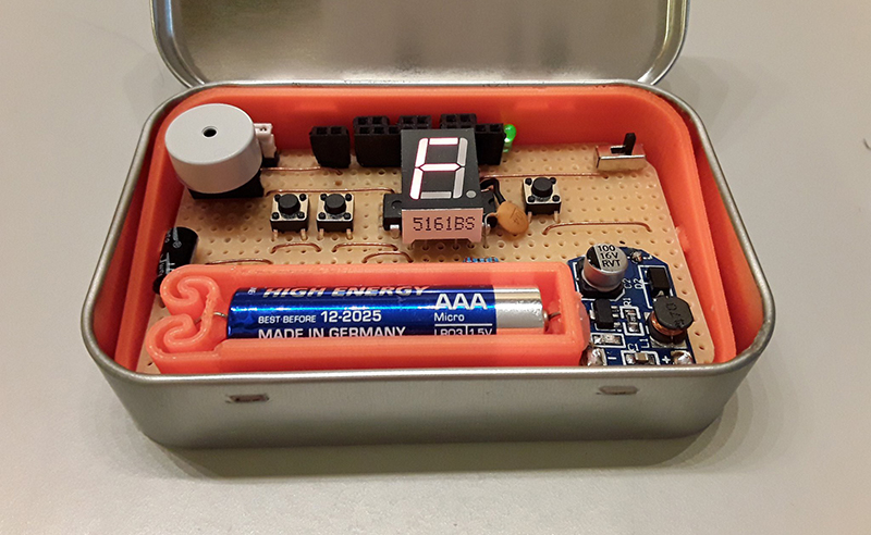
For [Dejan]’s entry to the Musical Instrument Challenge in this year’s Hackaday Prize, he’s tapping into some of the great work that has been done over the years to bring bleeps and bloops to the masses. He’s building a drum machine, a bass synth, and an arpeggiator that fits in your pocket, in a handy form factor that fits in an Altoids tin. It’s the FATCAT Altoids Tin Mod Tracker.
This is a simple build meant to fit in an Altoids tin, so you’re not getting a whole lot of hardware here. There’s a battery, there’s a boost circuit, and there’s a single chip, an ATtiny84. This tiny little microcontroller is the heart of the box, able to provide a drum track with a kick, snare, and a closed and open high hat. There’s a bass with a simple square wave and portamento, and an arp track that can be used as a lead or arpeggiated chords. All of this is programmed in C and uploaded straight to the chip.
The ATtiny series of microcontrollers are fairly popular for various means and methods of creating square wave bleeps and bloops. We’ve seen them become a MIDI synth that fits inside a MIDI jack, and we’ve seen how much chiptune goodness you can fit in thirty two bytes of RAM. Cornell even had a spat of rickroll vandalism with a coin cell throwie built on an ATtiny85. Anything that puts more ATtiny chiptunes into the hands of more people is great in our books, and this Altoids tin synth is just the thing.
You can check out a demo of the FATCAT below.


This project has Software Flow Charts, full State Machine diagrams and an extensive construction manual. The schematic is actually a full schematic rather than a glorified netlist.
This is how older and educated professionals document a project and is a good example of quality documentation.
It’s a pity that the schematic isn’t available as and image and PDF because it is very good example of a “readable” schematic instead of the all to common glorified netlists I see all the time now.
Well done.
As an amateur, I am suddenly supremely self-conscious of my schematic layout skills. I do try, keeping wires as short as possible and connecting logically distinct sections via named labels instead of wires, but I haven’t spent much time with “real” schematics.
My KiCad install isn’t liking the schematics linked in the documentation – I get a bunch of question marks.
I really do like that flowchart, though!
Readable, really?
The flow diagram is messy and not conventional, I can barely understand what is the sequence.
Yes, drawing are nice but that’s the only value.
I agree. While it is nice that there is a diagram at all over not having one, since it follows some random convention the author decided upon and not how everyone else does them it is rather cumbersome to try and follow. In my opinion this is not the mark of an “older and educated professional”. I’d give an ‘A’ for effort though, but definitely not the gold standard of documentation that ROB is ascribing (disclaimer: not that I am great at documentation either lol).
I agree… A schematic image or pdf would be appreciated.
For the curious –
http://hackaday.com/2018/10/27/chiptunes-in-an-altoids-tin/#comment-5358937
I’ll get it right this time :S
For the curious –
https://cdn.hackaday.io/images/7954321540712823865.png
Hey, thanks for the suggestion!
I’ve added a PDF of the circuit diagram to the project files section. While doing so I also noticed I’d made a mistake with pin 1 of the patchbay. So the diagram has been updated as of today.
https://cdn.hackaday.io/files/1613966905166464/FATCAT%20Circuit%20Diagram.pdf