As you may have noticed in our coverage, we’re big fans of OpenSCAD around these parts. The fact that several of the Hackaday writers organically found and started using the parametric CAD package on their own is not only a testament to our carefully cultivated hive mind but also to the type of people it appeals to. Hackers love it because it allows you to model physical objects as if you were writing software: models are expressed in code, and its plain text source files can be managed with tools like git and make. If you’re a real Pinball Wizard you could design objects and export them to STL without ever using a graphical interface.
 But as you might expect, with such power comes a considerable learning curve. OpenSCAD devotee [Uri Shaked] recently wrote in to share with us his workflow for designing complex interacting mechanisms, which serves as an excellent primer to the world of parametric design. From animating your models to recreating the “vitamins” of your build, his post contains plenty of tips that can help both new and veteran OpenSCAD users alike.
Perhaps the biggest takeaway from his post is that you should be thinking of your projects as a whole, rather than as individual models. [Uri] recalls his early attempts at designing mechanisms: designing each component individually, printing it out, and only then finding out if it fits together with the other pieces. This method of trial and error is probably familiar to anyone who’s designed their own 3D printed parts — but it’s slow and wastes materials. The alternative, as he explains it, is to design all of the pieces at the same time and “assemble” them virtually. This will allow you to check clearances and fitment without dedicating the time and materials to test it in the real world.
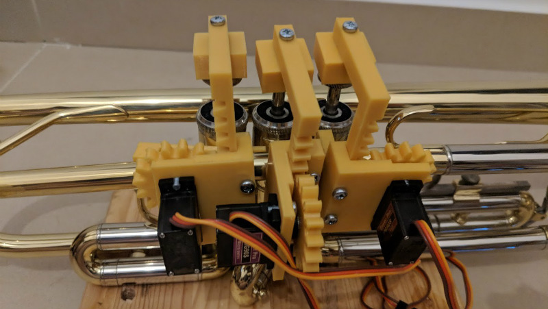
In fact, as [Uri] explains, you’re better off spending your time bringing real-world parts into OpenSCAD. By carefully measuring the hardware components you want to interact with (servos, gears, switches, etc), you can create facsimiles of them to use as a reference in your OpenSCAD project. As time goes on, you can build up your own library of drop-in reference models which will accelerate future designs.
He also spends a little time talking about something that doesn’t seem to be terribly well known even among the OpenSCAD converts: you don’t have to use the built-in editor if you don’t want to. Since OpenSCAD source code files are plain text, you can write them in whatever editor you like. The OpenSCAD model viewer even has an option specifically for this scenario, which will cause it to update the rendered preview as soon as it detects the source has been updated. For [Uri] this means he can create his designs in Visual Studio Code with a constantly updating preview in another window.
If you’re looking for examples of what the parametric capabilities of OpenSCAD can do for you, we’ve got no shortage of excellent examples. From creating customized computer cases to saving time by using mathematically derived components. Our very own [Elliot Williams] even has a write up about that most glorious of OpenSCAD commands: hull().


“If you’re a real Pinball Wizard you could design objects and export them to STL without ever using a graphical interface.”
I imagine POV-Rayers wouldn’t have a problem.
Hmm. If one is designing a complex 3d model via CLI in this day and age, I feel like they’re being willfully contrarian. Why would someone voluntarily subject themselves to such horrors from the past when there’s so many readily available alternatives? Would they also like to defecate into a pig toilet? Contract syphilis? Manually separate cotton?
Oh, AutoLisp isn’t that bad. :-)
I guess it depends how much you like text. I use both OpenSCAD and FreeCAD. The constraints solver in FreeCAD is lovely but sometimes I just want to write code to generate objects. The MCAD library is wonderful for generating worm gears that mesh perfectly with spur gears for example and I now know a lot more about circular pitch and involute gear profiles than I would have had I not gotten dirty with OpenSCAD
There is variety of masochist tasks – high heel in chest or cli cad, just don’t judge ;)
I will up you one better, I’ve recently made lampshade by writing python code to generate polygon points for openscad. It could be done, but I can’t imagine how I could do required shape (series of alternating bezier polylines) easily in point-and-click interface. Also making changes (like amount of segments) required just changing one parameter. You can of course change one parameter to change details in simple objects, but when you really do need “special” shapes you need expresiveness of programming language. Please read “In the beginning was the command line” from Neal Stephenson ( http://cristal.inria.fr/~weis/info/commandline.html – it’s free) if you want to really understand tradeoffs between gui and command line.
You remind me – I used to create 3D meshes from C code. Then I’d use POV-Ray to display the result.
Rather rough there – the fact is that GUI modelers are written in a CLI because there’s no good graphical interface for general purpose programming. Once one leaves trivial modeling, one needs to move to more capable tools. For example, I wrote software to evaluate the sweeping of a solid body along a specific type of trajectory, a task that cannot currently be done in any GUI. That was 30 years ago; I’m still waiting for the GUIs to catch up.
This is why most modelers are hybrids – offering both some version of a CLI along with the GUI.
One issue that still remains with designing your parts as assemblies is 3d printer tolerances. Getting a good snap-fit can still require trial and error to get a good fit, and it depends on the printer, material, etc.
Exactly!
I can imagine someone reading this, then designing some great big complex multi-parted project in OpenSCAD. Proudly printing all the pieces out sure it’s going to be perfect on the first try…
and then crying because absolutely NOTHING fits together!
Your real life plastic will expand a bit after extrusion and warp a little while it cools. Your slicer will try to account for this but there are sooo many variables, variance in filament, air temperature/pressure, wind currents, the phase of the moon, etc… Holes will always be a little smaller than they are supposed to be. Teeth will be a little tighter, etc…
Unless you are willing to spend a lot of time sanding, drilling and filing or you are willing to guess high on the amount of slop needed so that your prints are guaranteed to go together but unlikely to do so very precisely…
plan on spending some time tweaking and re-printing.
But.. I will agree, at least checking that your design fits together on the computer could eliminate an iteration or two vs just winging it!
How old/cheap is your 3D printer? Even a fairly low end machine should have dimensional tolerances within 0.2 mm. Plus materials like PLA and PETG have shrink factors that are low enough to be negligible.
There’s absolutely no reason your physical models shouldn’t fit together the same way they do virtually in the CAD program. If they don’t, something is wrong.
In such a case, parts should be designed with larger tolerances. There are libraries for mechanical parts out there which already consider those (e.g. variable “spiel” = “tolerance” in the following library, line 41):
https://www.thingiverse.com/thing:1604369
Is OpenSCAD still single-threaded? That immediately disqualifies it for any serious work. Few years ago a friend of mine spent months building a project with it and then had to abandon OpenSCAD because it would crawl to a halt with large assemblies. He used some web-based CAD system to finish his project. It’s weird that a web app would be faster than a native program… but I guess anything’s possible nowadays.
OpenSCAD is based on CGAL, which is not really optimized for CAD. It melts down pretty quickly, especially if you have a lot of curves.
Your friend probably used OnShape, which is based on Parasolid and D-Cubed. Both of these are commercial kenels used several different packages that are heavily optimized for CAD, with long development histories. That’s why the performance is so much better, unfortunately OpenSCAD just isn’t as optimized.
Not that I’m hating on it, I love OpenSCAD and think it’s a great triumph of open source. You can’t really expect it to compete with commercial products with decades of development, at least not yet.
Do all of your work with `$fs` and `$fa` set to coarse values and then only crank up your detail when you’re ready for an STL
It still can take freaking forever to do your final render to STL with even modestly complex geometries.
There aren’t any major multi-threaded CAD systems. The data structures that are created and managed would become far too complex if the modelers had to have record and memory locking. What is usually a problem is the underlying record keeping and naive record access algorithms. There are multithreaded FEA solvers and image generation, because the type of problem allows it to be subdivided, but that is a far different case than CAD.
For example:
https://knowledge.autodesk.com/support/autocad/learn-explore/caas/sfdcarticles/sfdcarticles/Multithreading-or-multiprocessor-capabilities.html
https://forums.autodesk.com/t5/autocad-electrical-forum/why-don-t-autocad-focus-on-multicore-processor-support/td-p/7286313
https://blog.bricsys.com/cpus-for-cad/
Even Solidworks:
https://www.javelin-tech.com/blog/2010/11/do-multi-core-processors-help-with-solidworks/ does background operations based on
There are peripheral functions, but not for the primary CAD solver.
I like OpenSCAD a lot. Will it be around in the future though?
I’ve had a few people tell me that OpenSCAD was old news, that everything has shifted over to FreeCAD. I thought all that mouse-based stuff was better for making art and not as good for parametric designs and parts that needed to fit together. It was pointed out to me that FreeCAD can run OpenSCAD code to provide those things.
I don’t really know about this, I haven’t learned FreeCAD yet. Also, I don’t run into a lot of FreeCAD designs being shared on the internet the way I do OpenSCAD ones. I mostly dismissed this and put FreeCAD on the “to learn” list, somewhere after memorizing the rest of OpenSCAD’s manual.
Then.. the other day I was waiting for a long render in OpenSCAD. And waiting. And waiting. I checked top and was surprised to see only one core working! So I did some Googling and lo and behold.. OpenSCAD only knows how to use one core at a time. Yikes! That’s a pretty glaring limitation for almost 2019! Who is using a one-core computer for 3d design now anyway?!?!
The other thing I found while googleing that day was Implicit CAD. Implicit CAD uses it’s own renderer, which is multi-core enabled but attempts to be compatible with OpenSCAD code. Perfect! It turns out it has been reviewed here on HaD too, I don’t know how I missed that.
On the downside, Implicit CAD seems to be pretty much in it’s early days. It seems to be available only as source code and isn’t even in any Linux distribution’s package managers yet. Also it has no editor of it’s own. Well. maybe that last one is an advantage though. How many programs that are not editors but contain editors have good ones anyway?!? I’m looking at you Arduino!
So.. uh.. yah… Is OpenSCAD part of the future or just a stop-gap until Implicit CAD is ready? I think I read on OpenSCAD’s bugzilla that multi-threading it would be a major undertaking.
SolveSpace:
https://en.wikipedia.org/wiki/SolveSpace
It’s still too buggy for prime time, but I loved the potential when I wasn’t screaming at my screen.
Tried it. The error dialogs are …punishing. And they are modal, so you have to clear them (mulitple times) just to get back to the workspace. And they are in SolveSpace gobbledygook, totally unhelpful to a beginner.
If they reworked the SolveSpace error flow, I’d perhaps give it another go, but it’s going to take a lot to get me away from OpenSCAD.
I seriously hope that OpenSCAD does not have much of a future. OpenSCAD is based around constructive solid geometry(CSG), which was developed in the 1970s. We have made quite a bit of progress in CAD technology since then and while modern CAD software uses CSG, there is so much more to modern CAD than CSG. In addition, OpenSCAD should not be considered a parametric modeller, because one cannot define the position of geometric features with respect to each other. For example, OpenSCAD does not natively support making a hole a certain distance away from the horizontal and vertical sides of a rectangle, so that a hole may be located in a corner. Sure you can implement such a thing in OpenSCAD, but it is very difficult to do so, especially we want to resize the dimensions of our rectangle. Things can get even more complicated if we make a geometric feature that is dependent on the holes dimension. In the end, we will be doing manually what FreeCAD does automatically. The main thing one should understand about modern parametric modelling software is that it embodies the idea of geometric constraints that Ivan Sutherland’s Sketchpad used:
https://en.wikipedia.org/wiki/Sketchpad
https://www.youtube.com/watch?v=5RyU50qbvzQ
Notice how fast Sutherland is able to define shapes? Just because one is using the mouse doesn’t mean one is making art. I’d also argue that because one is directly using geometric constraints, that this is a better approach for making parts that fit together.
That being said, FreeCAD and other open source CAD software still has a ways to go to reach parity with commercially available CAD software. There are a number of problems with FreeCAD that will require a lot of work fix, especially those related to the OpenCASCADE CAD kernal.
Since the locations are parametric, the offsets can be parametric as well. I glanced at the syntax, but it looks like the following is close enough:
distx = 10;
disty = 10;
rectx = 100;
recty = 80;
cube(distx, disty, thickness);
translate( [distx, disty, 0])
cylinder(…);
translate ( [distx, recty-disty,0])
cylinder(…);
translate ([rectx -distx, disty,0])
cylinder(…);
translate ([rectx-distx, recty-disty,0])
cylinder(…)
So any change to the rectangle size maintains the locations of the holes specified by the cylinder commands relative to the faces/corners.
Not a surprise that usability is not the same as software that took tens to hundreds of millions of dollars to develop.
Ha – cube(rectx, recty, thickness);
I suppose if you consider simple mathematics “very difficult to do” you might have a point. But then, you probably aren’t the target user for OpenSCAD in that case.
It would be nice to have a CAD package that also has graphical tools to write and edit the code automatically. Best of both worlds?
OpenSCAD is like GNU/Turd – ambitious but rubbish.
Didn’t know this existed. As a ‘coder’, this looks interesting. My son has a 3D printer, so I might just have a go at trying to generate a simple part with it. Lego Block? Yeah I know that’s been done many times but may be a ‘useful’ way to start learning OpenSCAD as it is a ‘simple’ shape.
Not multi-threaded? And here I though ‘maybe’ I could give my Ryzen 5 2600 a workout :) .
According to a search there is an OpenSCAD module under development for FreeCAD.
FWIW, Thingiverse’s ‘Customizer’ uses specially formatted OpenSCAD scripts that you can download. If you look for ‘parametric LEGO’, you’ll find lots of code that you can reuse.
In case it helps anyone, here is the header I use with my OpenSCAD scripts: https://pastebin.com/fnTwe9rV
As a concept, I like OpenSCAD. But, it needs some object orientation before I think it’s ready for prime time (along with the multi-threaded thing).
I sincerely believe people are missing an important point ablu OpenScad : It allows you to plan the maching of your piece as if you actjally were working with solid , real objects, and real tools. You can imagine (and type a script) which takes a wooden piece and drills hole a in it. You can forget about the round interruption in one of the surfaces, the tunnel, and the bottom of the pocket. You dont need to draw all that (like in -say- ACad.) You just drill. You use the same reasoning as in the workshop. You dont need to worry about making the results explicit. You only explicit and script the machining process. For me, this ” other way around ” of thinking is VERY much straightforward.
ablu = about;
maching = machining
actjally = actually